Tuned Aircraft Lighting for an Improved Flight Experience

a technology for aircraft and flight experience, applied in the field of aircraft lighting, to achieve the effect of improving overall well-being and flight experien

Active Publication Date: 2017-11-16
THE BOEING CO
View PDF8 Cites 4 Cited by
  • Summary
  • Abstract
  • Description
  • Claims
  • Application Information

AI Technical Summary

Benefits of technology

[0003]In one illustrative example, an apparatus comprises a lighting system and a control system that controls operation of the lighting system. The lighting system is comprised of a set of light devices capable of emitting light of different wavelengths and positioned within an interior of an aircraft. The control system that controls operation of the lighting system creates different light scenes during different periods of flight of the aircraft. The different light scenes and the different periods of flight are selected to improve an overall well-being and flight experience of persons onboard the aircraft during a flight of the aircraft. The different light scenes comprise a first light scene, a second light scene, and a third light scene. The first light scene has a first spectral distribution that includes a first light having a first wavelength between about 436 nanometers and about 486 nanometers. The second light scene has a second spectral distribution that includes a second light having a second wavelength between about 606 nanometers about 656 nanometers. The third light scene has a third spectral distribution that includes a third light having a third wavelength between about 530 nanometers and about 580 nanometers.
[0004]In another illustrative example, a method is provided for emitting different types of light during a flight of an aircraft. Light is emitted from a lighting system comprised of a set of light devices positioned within an interior of the aircraft. Operation of the lighting system is controlled to create a first light scene during a first set of periods of flight. The first light scene has a first spectral distribution that includes a first light having a first wavelength of between about 436 nanometers and about 486 nanometers. Operation of the lighting system is controlled to create a second light scene during a second set of periods of flight. The second light scene has a second spectral distribution that includes a second light having a second wavelength between about 606 nanometers to about 656 nanometers. Operation of the lighting system is controlled to create a third light scene during a third set of periods of flight. The third light scene has a third spectral distribution that includes a third light having a third wavelength between about 530 nanometers and about 580 nanometers. Creating different light scenes at different periods of flight improves an overall well-being and flight experience of persons onboard the aircraft during the flight.
[0005]In yet another illustrative example, a method is provided for emitting different types of light during a flight of an aircraft. Light is emitted from a lighting system comprised of a set of light devices positioned within an interior of the aircraft. Operation of the lighting system is controlled according to a selected schedule for generating different light scenes during different periods of flight to improve an overall well-being and flight experience of persons onboard the aircraft during the flight. Each of the different light scenes has a unique spectral distribution. The selected schedule includes a first light scene having a first spectral distribution that includes a first light having a first wavelength of between about 436 nanometers and about 486 nanometers. The selected schedule includes a second light scene having a second spectral distribution that includes a second light having a second wavelength between about 606 nanometers to about 656 nanometers.

Problems solved by technology

Further, passengers may become more attentive or they may wakeup from their sleep when it is time to land or when meals are being served.

Method used


Image

  • Tuned Aircraft Lighting for an Improved Flight Experience
  • Tuned Aircraft Lighting for an Improved Flight Experience
  • Tuned Aircraft Lighting for an Improved Flight Experience

Examples


Embodiment Construction

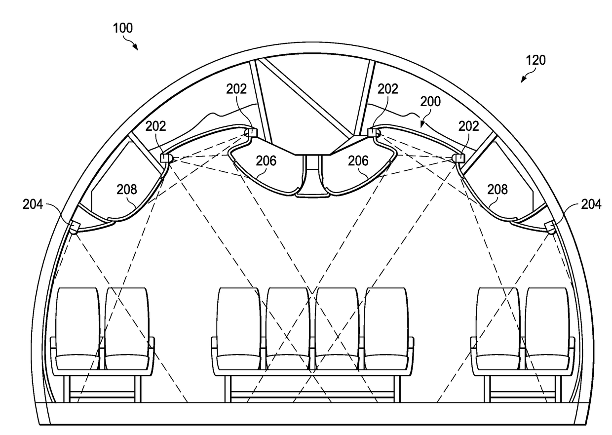
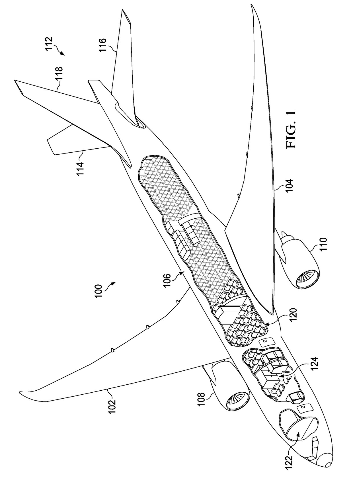
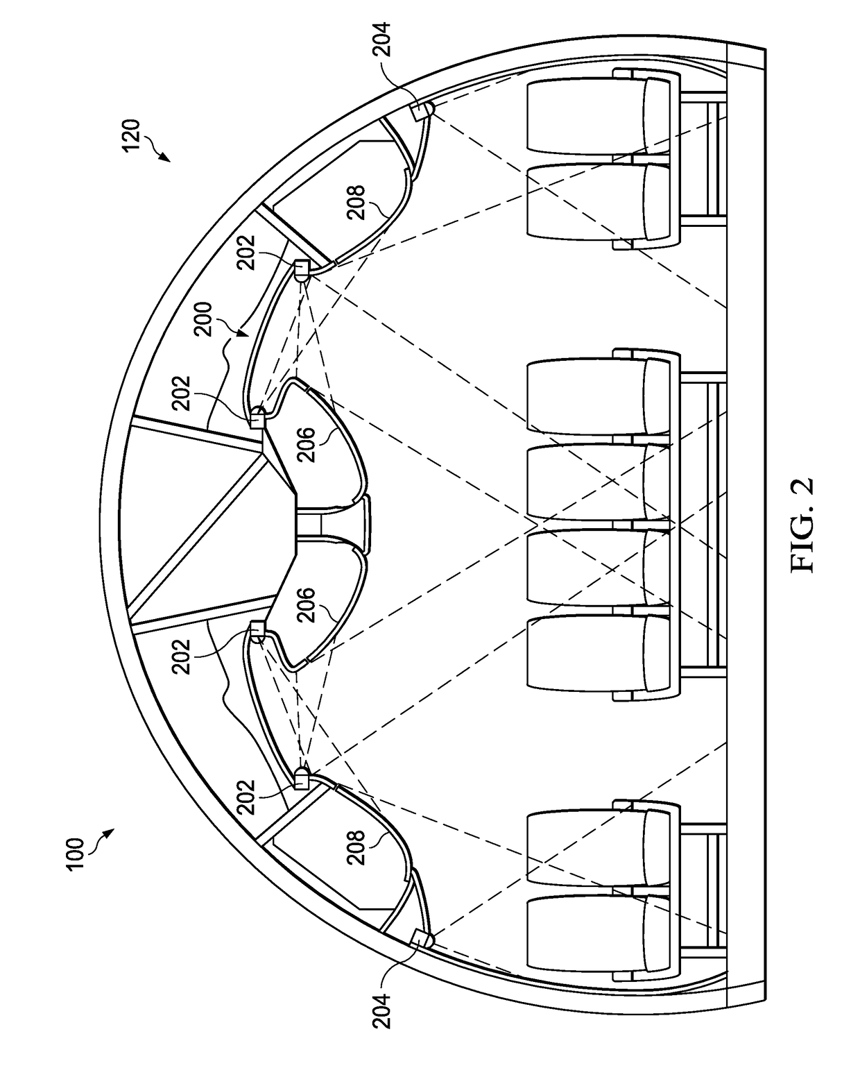
[0019]The illustrative examples recognize and take into account different considerations. For example, the illustrative examples recognize and take into account that it may be desirable to create different light scenes during a flight of an aircraft using light that is chosen to improve an overall experience and well-being of persons onboard the aircraft. In particular, the illustrative examples take into account that light of certain wavelengths may allow a passenger of an aircraft to experience certain phases of flight in an improved manner.

[0020]Thus, the illustrative examples provide a method and apparatus for emitting light during a flight of an aircraft to create different light scenes during different periods of flight. In one illustrative example, a method is provided for emitting different types of light during a flight of an aircraft. Light is emitted from a lighting system comprised of a set of light devices positioned within an interior of the aircraft. Operation of the ...


PUM


Abstract

A method and apparatus for managing lighting during a flight. Light is emitted from a lighting system comprised of light devices positioned within an interior of the aircraft. Operation of the lighting system is controlled to create a first light scene, a second light scene, and a third light scene. The first light scene has a first spectral distribution that includes first light having a first wavelength of between about 436 nanometers and about 486 nanometers. The second light scene has a second spectral distribution that includes second light having a second wavelength between about 606 nanometers to about 656 nanometers. The third light scene has a third spectral distribution that includes third light having a third wavelength between about 530 nanometers and about 580 nanometers. Creating different light scenes during different periods of flight improves an overall well-being and flight experience of persons onboard the aircraft during the flight.

Description

BACKGROUND INFORMATION1. Field[0001]The present disclosure relates generally to aircraft lighting and, in particular, to lighting within an interior of an aircraft. Still more particularly, the present disclosure relates to a method for controlling the lighting in an aircraft to create different light scenes during different periods of flight to improve an overall flight experience of persons onboard the aircraft.2. Background[0002]Passengers onboard an aircraft may participate in various activities during the flight of the aircraft. For example, prior to a taxiing phase of flight or a takeoff phase of flight, passengers may be fastening their seat belts, adjusting their seats, walking through the aisles, or engaging in other activities. During a cruise phase of flight, passengers may choose to relax or rest. For example, in some cases, some passengers may choose to sleep during a large portion of the cruise phase of flight when flying overnight. Further, passengers may become more ...

Claims


Application Information

Patent Timeline
Patent Type & Authority Applications(United States)
IPC IPC(8): B64D11/00H05B37/02
CPCB64D11/00H05B37/0281B64D11/003B64D2011/0076B64D2011/0038B60Q3/43B60Q3/47Y02B20/40H05B47/16
Inventor BECKMAN, JOHN CHRISTIAAN
Owner THE BOEING CO
Why Eureka
Try Eureka