
Method of partitioning a set-associative cache in a computing platform

a computing platform and cache technology, applied in the field of computing platform set-associative cache partitioning, can solve the problems of prohibitively expensive hardware solutions, unpredictable performance of software components, and large contentions

Inactive Publication Date: 2017-11-16
GE AVIATION SYST LLC
View PDF2 Cites 6 Cited by
  • Summary
  • Abstract
  • Description
  • Claims
  • Application Information

AI Technical Summary

Benefits of technology

The patent describes a method for optimizing the use of a cache in a computer system. The method involves identifying the cache's capacity based on hardware specifications, and then assigning a specific cache space to each software component based on its demand. The method also involves creating a template for mapping the components' RAM to the dedicated cache space, which reduces contention and improves performance during execution. The technical effect of this method is improved performance and efficiency in computer systems, particularly in avionics architectures for aircraft.

Problems solved by technology

Because RAM is typically allocated to a variety of software components without referencing the RAM / CACHE mapping, contention may result, causing unpredictable performance for a software component such as an application, a task, or a thread.
In particular, some computer platforms, such as integrated modular avionics (IMA) architectures, may have software components that need to operate deterministically and for which contention is a larger problem.
However, a hardware solution may be prohibitively expensive, particularly for a product having a low volume in the commercial marketplace.
However, other computer resources, such as one or more caches, may still be shared and cause contention.
Unfortunately, periodically setting up and tearing down the time partition may slow execution time for a critical software component.

Method used


Image

  • Method of partitioning a set-associative cache in a computing platform
  • Method of partitioning a set-associative cache in a computing platform
  • Method of partitioning a set-associative cache in a computing platform

Examples


first embodiment

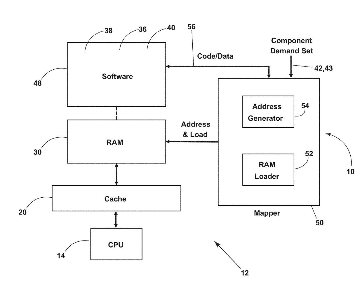
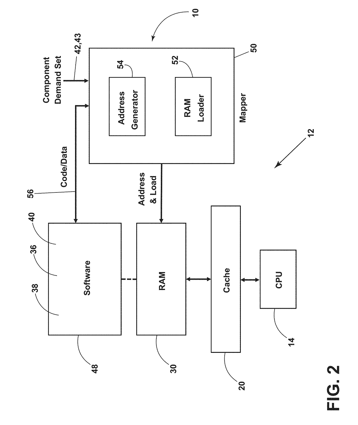
[0017]Referring now to FIGS. 2-4, in the present disclosure, a method 10 of partitioning a set-associative cache is described. A computer platform 12 (FIG. 2) may include a component storage device 48 holding a plurality of software components 40 to be loaded into a RAM 30 by a mapper 50 executing partitioning method 10. Cache 20 may be an L1 cache embedded with CPU 14 or may be an L2 cache outboard of CPU 14. In addition, cache 20 may be an L3 cache and which may be shared by two or more CPU cores. Other layers (L) of cache may be utilized. The purpose of partitioning method 10 may be to form a template for mapping software components or groups of components to dedicated sets 28 (FIG. 4) of the set-associative cache 20. In addition, the purpose of partitioning method 10 may be to load a plurality of software components or groups of components into RAM 30 such that cache 20 is spatially partitioned for software components needing deterministic performance. Although the following des...

second embodiment

[0026]Referring to FIGS. 5 and 6, method 10 of partitioning a set-associative cache for a plurality of software components to be loaded into RAM may comprise reserving a set in the set-associative cache for a software component not within the plurality of the software components. Like the algorithm of FIG. 3, a cache height 26 may be calculated from the hardware specifications of computing platform 12 (step 201). In addition to identifying the software components 30, step 202 may distinguish booted components 36 from future components 38 (FIG. 6), where one or more software components may be loaded into RAM after computer platform 12 is operating and where partitioning method 10 maps future components 38 to reserve sets of cache 72. Next, step 203 may determine a component demand set 42 for the booted components 36 and may include determining a reserve demand set 43 (FIG. 2) for future components 38, where the RAM blocks 32 corresponding to future components 38 are not loaded by RAM...

third embodiment

[0028]Referring now to FIG. 7, partitioning method 10 may comprise mapping the code / data 56 of various software components 40 to L1 caches 60 and L2 cache 62. Components 40 are shown in relative size of code / data and may include tasks (T), processes (P), operating systems (OS), and cores. The dimensions of caches L1 and L2 may represent the number of sets 22 available in each cache 20. In this example, a component fraction (tabulated in percentages) may be determined for tasks 1-16 and mapped proportionally to the three caches 20. Note that T1, T8, T15, and T16 may each be given a dedicated set 28, while two groups of components (T2-T7 and T9-T14) may collectively share a dedicated set 28. In this example, a software component 40 may be mapped to two caches (although a RAM is not shown in this figure). However, a cache may not be mapped to two RAM blocks because CPU 14 may not then know which RAM to go to for source code / data. The method 10 of cache partitioning may be the same for ...


PUM


Abstract

A method of partitioning a set-associative cache for a plurality of software components may comprise identifying a cache height equal to a number of sets in the set-associative cache based on hardware specifications of a computing platform. The method may further comprise determining at least one component demand set of the plurality of software components and dedicating a set in the set-associative cache for the at least one component demand set. The method may further comprise assembling a proportional component sequence of the at least one component demand set having a sequence length equal to an integer submultiple of the cache height. The method may further comprise concatenating assembled proportional component sequences to form a template for mapping a RAM to the dedicated sets in the set-associative cache.

Description

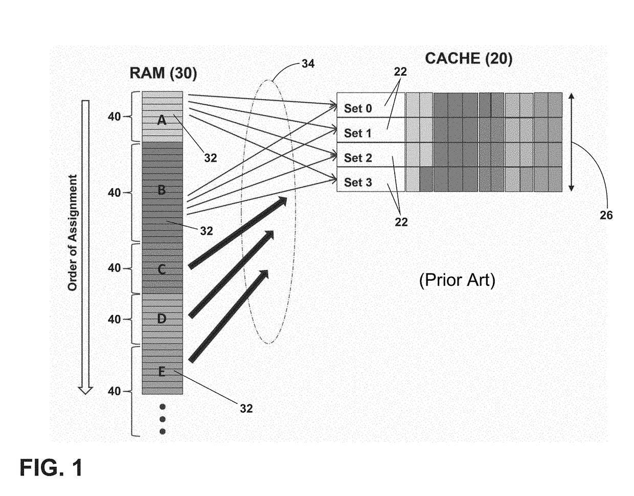
BACKGROUND OF THE INVENTION[0001]A computer platform with a set-associative cache may experience contention among multiple software components executing on the platform when more than one block of RAM (random access memory) is assigned to a common set of the cache. For example, the hardware of the computer platform may specify that hundreds or thousands of RAM blocks be serially assigned to each cache set, the assignment circling over the cache many times until each block of RAM is assigned. Because RAM is typically allocated to a variety of software components without referencing the RAM / CACHE mapping, contention may result, causing unpredictable performance for a software component such as an application, a task, or a thread. One solution to hardware-caused contention is to increase the number of lines in each set of the cache, each line being capable of holding a block of code or data attempting to utilize that set of cache. However, each set of the cache may still be assigned to...

Claims


Application Information

Patent Timeline
Patent Type & Authority Applications(United States)
IPC IPC(8): G06F12/0864G06F12/0897
CPCG06F12/0864G06F12/0897G06F2212/601G06F12/0848G06F12/0857G06F2212/1021G06F2212/1041
Inventor GOEBEL, CHRISTOPHER JOHN
Owner GE AVIATION SYST LLC
Learn More