Power source device

a power source and power supply technology, applied in the direction of vent arrangements, cell components, batteries, etc., can solve the problem of difficulty in specifying the position in which the gas is discharged

Active Publication Date: 2017-11-16
SANYO ELECTRIC CO LTD
View PDF6 Cites 9 Cited by
  • Summary
  • Abstract
  • Description
  • Claims
  • Application Information

AI Technical Summary

Benefits of technology

[0010]According to a configuration of a power source device mentioned above, gas discharged from an outer casing of a pouch cell is discharged from an exhaust port of a housing member en

Problems solved by technology

Therefore, in the pouch cell, it is difficult to

Method used


Image

  • Power source device
  • Power source device
  • Power source device

Examples


Embodiment Construction

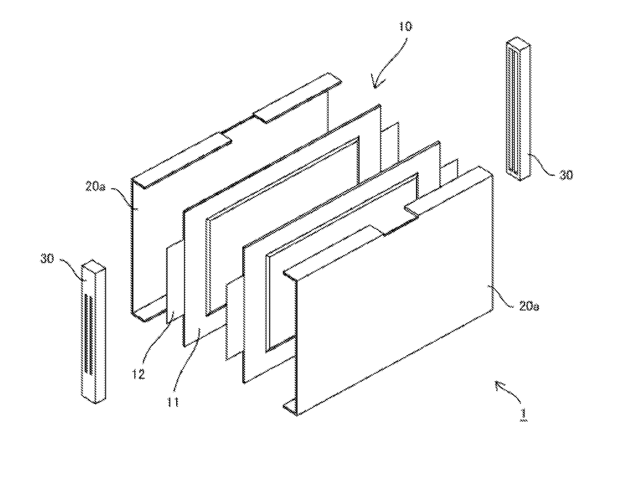
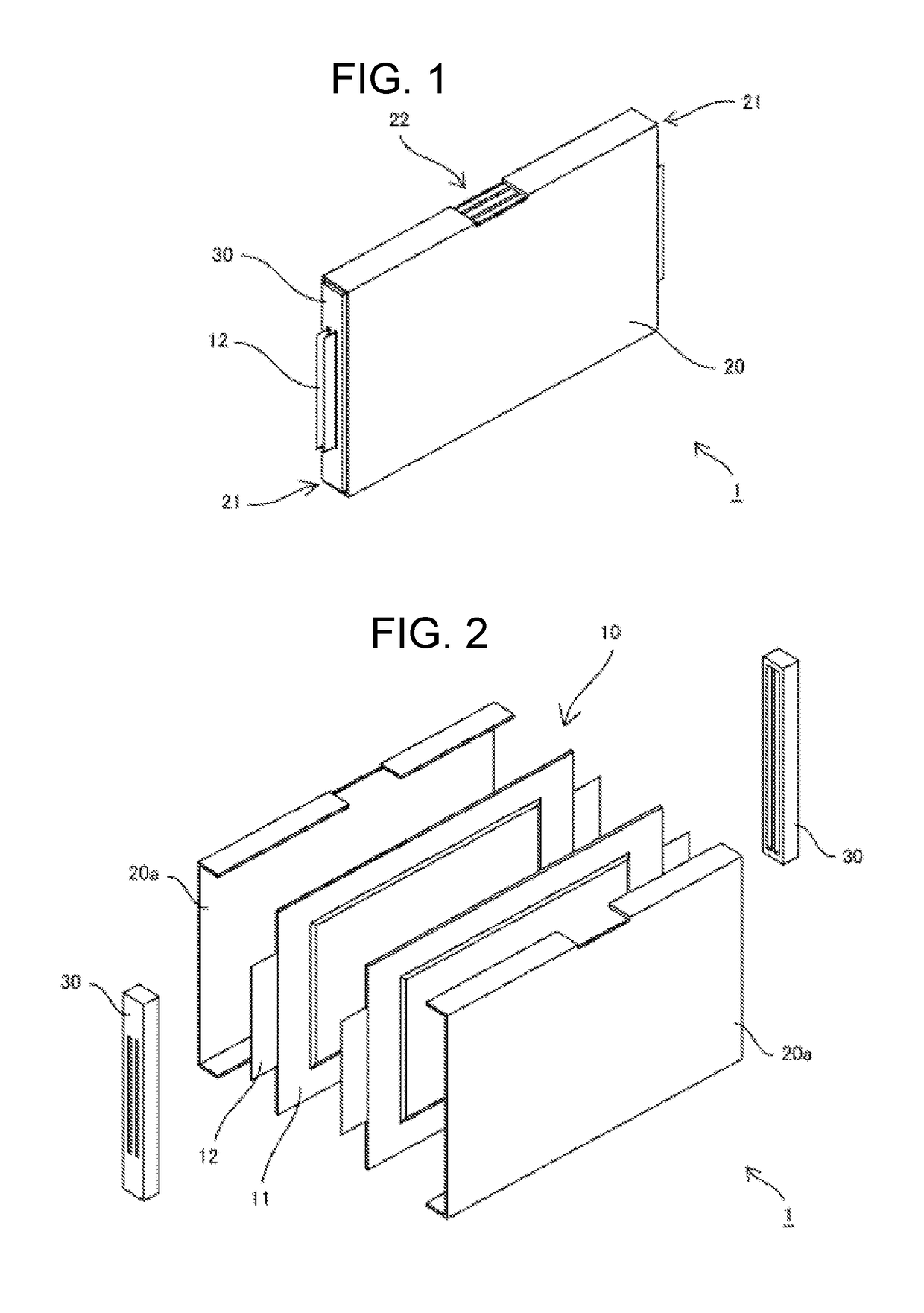
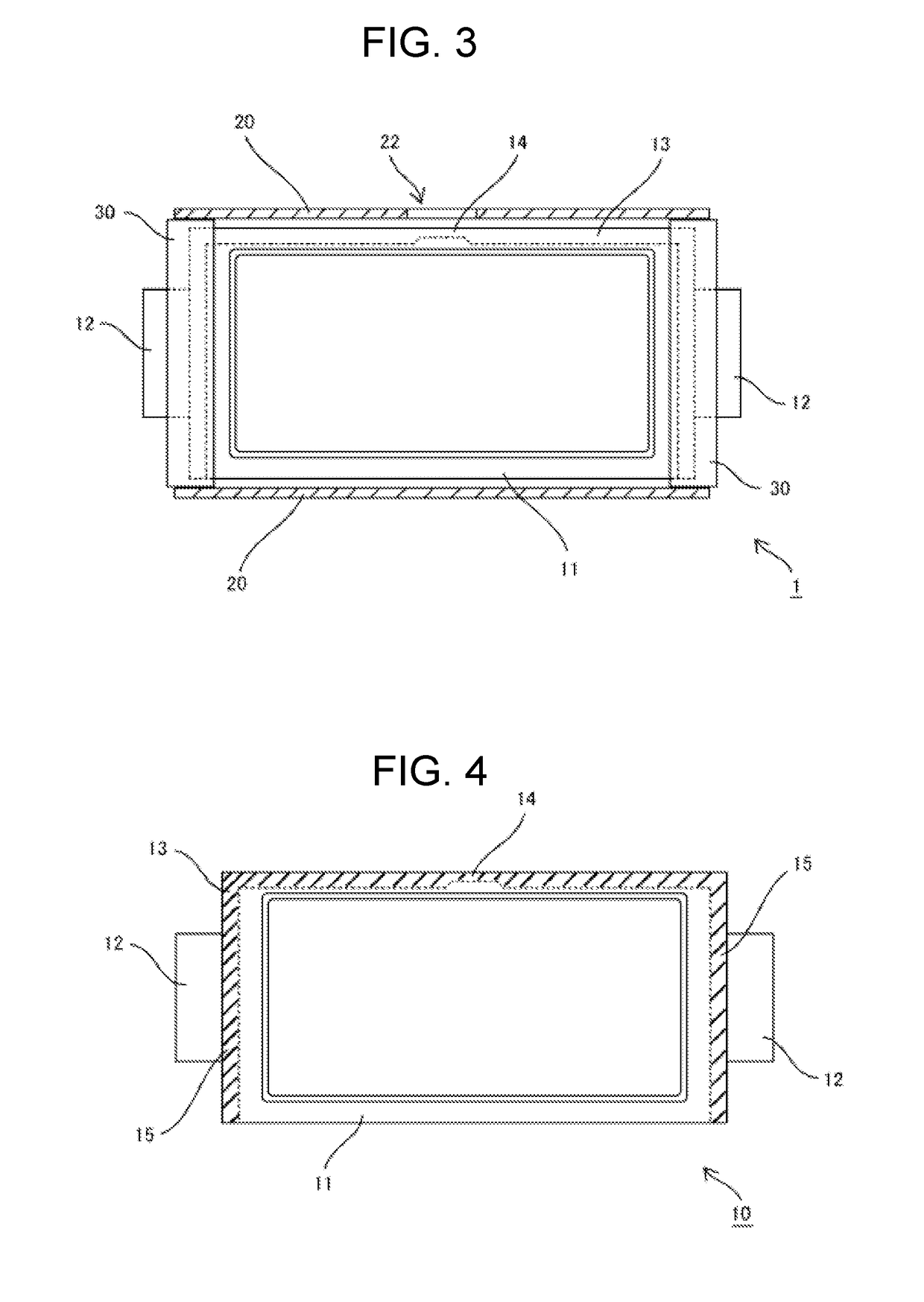
[0024]Power source device 1 in accordance with a first exemplary embodiment of the present invention is described below in detail with reference to FIGS. 1 to 4. Power source device 1 shown in FIGS. 1 to 3 include a plurality of pouch cells 10, housing member 20 having a tubular outer shape, and a pair of resin members 30 fitted to housing member 20. A plurality of pouch cells 10 is disposed inside housing member 20. As pouch cell 10, a lithium ion battery, a nickel hydrogen battery, and other various secondary batteries can be used.

[0025]As shown in FIG. 4, pouch cell 10 includes outer casing 11 formed of a deformable laminated film, a power-generating element enclosed inside outer casing 11, and a pair of electrode tabs 12 for outputting electric power generated by the power-generating element. The power-generating element includes an electrode body, an electrolyte solution, and the like. Electrode tab 12 is an output terminal of pouch cell 10, and is derived from the inside of ou...


PUM


Abstract

In order to allow gas discharged from a pouch cell to be guided to a predetermined position, a power source device includes one or a plurality of pouch cells (10) having laminated film outer casing (11), and a housing member (20) enclosing the one or multiple pouch cells (10). The one or plurality of pouch cells (10) each includes thermally welded portion (13) formed by thermally welding the laminated film, and gas discharge portion (14) provided in at least a part of thermally welded portion (13). Housing member (20) includes exhaust port (22) communicating with gas discharge portion (14) of one or a plurality of pouch cells (10).

Description

TECHNICAL FIELD[0001]The present invention relates to a power source device.BACKGROUND ART[0002]In recent years, an electrically-driven vehicle equipped with a power source device including a plurality of battery cells as a power source for motor of a hybrid car or an electric vehicle has been popular. Furthermore, a power source device used for a storage system combined with a generator such as a solar cell and storing electric power generated by the generator has been also known. In these power source devices, as the battery cell, for example, chargeable and dischargeable secondary batteries such as a lithium ion battery and a nickel hydrogen battery are used.[0003]Examples of the battery cell include a prismatic cell including an outer casing made of a metal outer can, a pouch cell including an outer casing made of a thin laminated film and having low rigidity, and the like. When a battery cell is in an abnormal state, an internal pressure of the battery cell increases and gas is...

Claims


Application Information

Patent Timeline
IPC IPC(8): H01M2/12H01M2/10H01M50/211H01M50/291H01M50/358H01M50/367
CPCH01M2/1241H01M2/1077H01M2220/20Y02E60/10H01M50/30H01M50/3425H01M50/367H01M50/291H01M50/358H01M50/211
Inventor HASHIMOTO, HIROYUKIOCHI, SHINGOHORIUCHI, TATSUHITO
Owner SANYO ELECTRIC CO LTD
Why Eureka
Try Eureka