
Rotor of rotary electric machine, rotary electric machine, and method of manufacturing rotor of rotary electric machine

Active Publication Date: 2017-11-16
HONDA MOTOR CO LTD
View PDF8 Cites 5 Cited by
  • Summary
  • Abstract
  • Description
  • Claims
  • Application Information

AI Technical Summary

Benefits of technology

The patent describes a rotor for a rotary electric machine that is both efficient and lightweight. This means that the rotor can generate a lot of power while also being very light.

Problems solved by technology

However, because aluminum is a conductor, when an end plate is formed of aluminum, there is concern of an Eddy current being generated in the end plate and efficiency of the rotary electric machine decreasing.
Since aluminum has a large specific gravity, there is concern of the weight of the rotor increasing.

Method used


Image

  • Rotor of rotary electric machine, rotary electric machine, and method of manufacturing rotor of rotary electric machine
  • Rotor of rotary electric machine, rotary electric machine, and method of manufacturing rotor of rotary electric machine
  • Rotor of rotary electric machine, rotary electric machine, and method of manufacturing rotor of rotary electric machine

Examples


Embodiment Construction

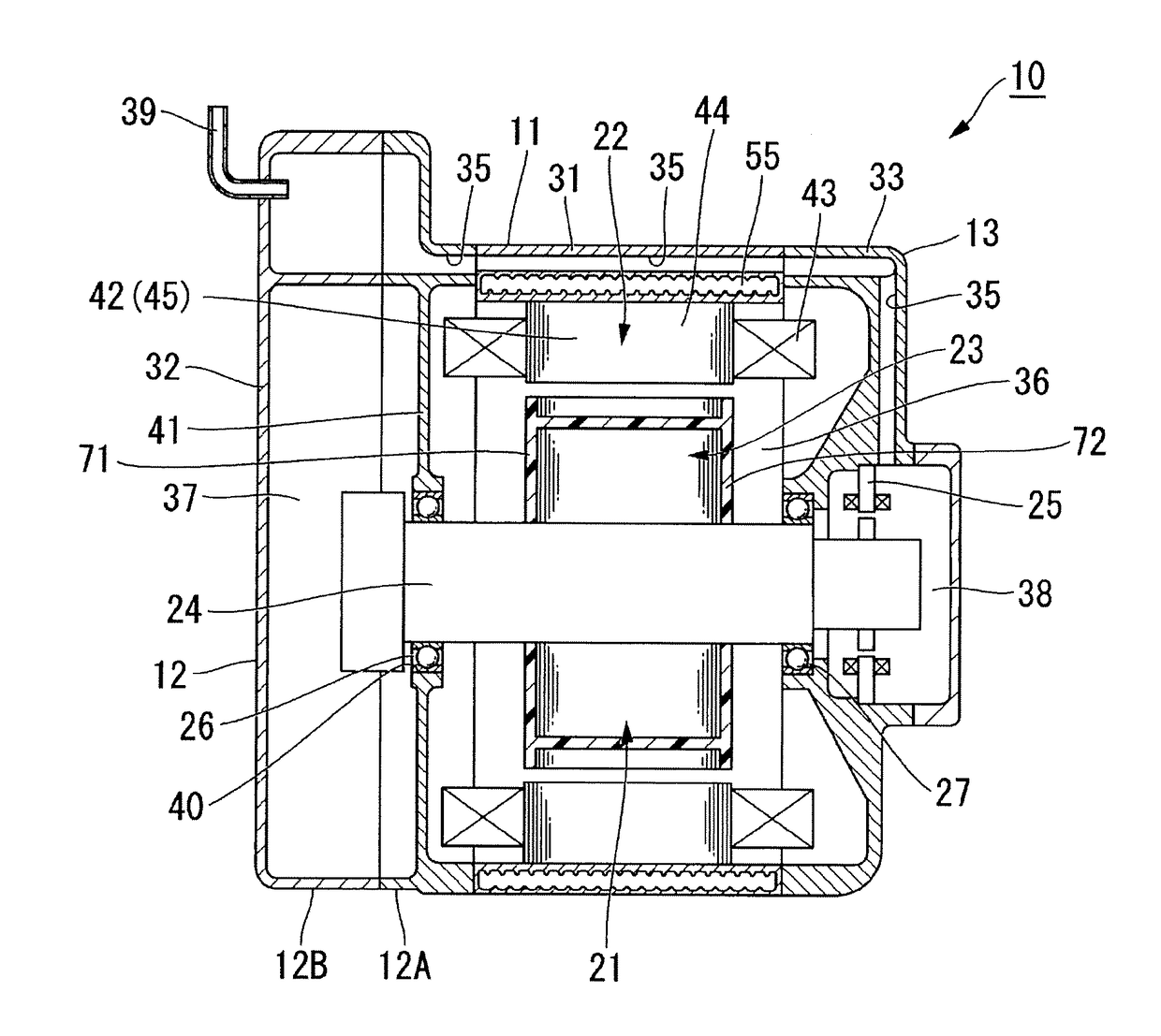
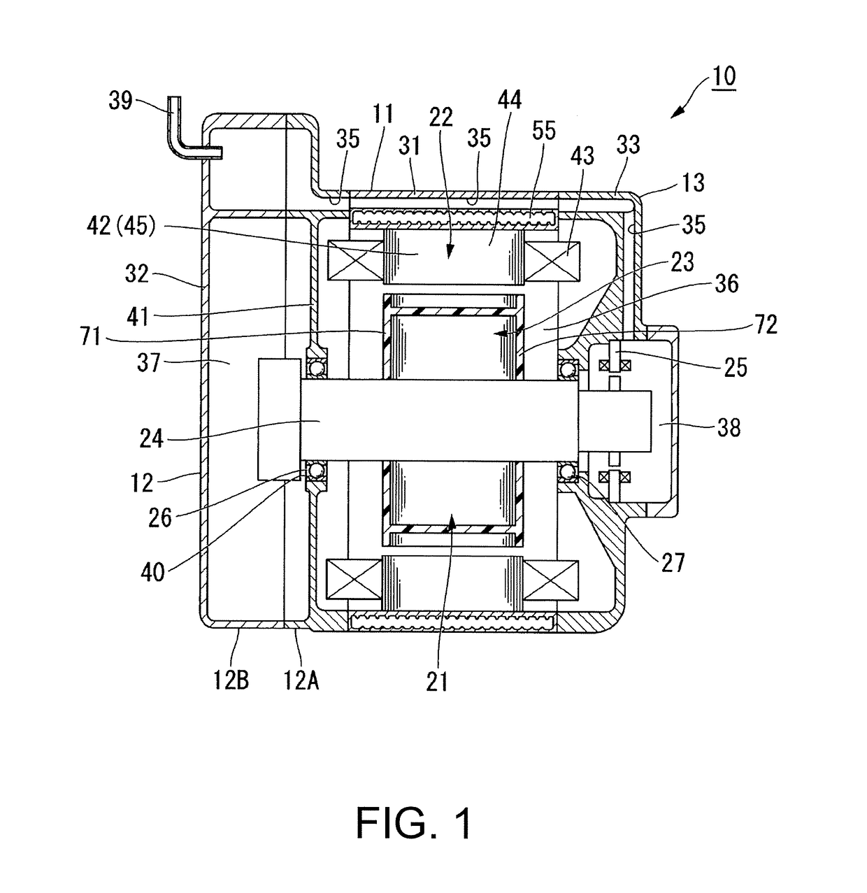
[0041]Hereinafter, an embodiment of the disclosure will be described with reference to the accompanying drawings. A motor which is employed as a rotary electric machine by a drive motor unit for an automobile will be described in the embodiment. In the following description, an axial direction of a rotary shaft of the motor is simply referred to as an “axial direction,” a circumferential direction of the rotary shaft is simply referred to as a “circumferential direction,” and a direction perpendicular to the axial direction and extending radially from the rotary shaft is simply referred to as a “radial direction.”

[0042]First, a drive motor unit 10 (hereinafter referred to as a “motor unit”) for an automobile according to the embodiment will be described below.

[0043]FIG. 1 is a cross-sectional view schematically illustrating a configuration of the motor unit.

[0044]As illustrated in FIG. 1, the motor unit 10 includes a motor housing 11 in which a motor 23 including a rotor 21 and a st...


PUM


Abstract

In a rotary electric machine that has excellent efficiency and light weight, a rotor (21) of a motor (23) includes a rotary shaft (24), a rotor core (61) that is fixed coaxially to the rotary shaft (24) and formed of electromagnetic steel, a first end plate (71) that is disposed to face a first end face (61a) of the rotor core (61), and a second end plate (72) that is disposed to face a second end face (61b) of the rotor core (61). The first end plate (71) and the second end plate (72) are formed of a bond magnet.

Description

CROSS-REFERENCE TO RELATED APPLICATION[0001]This application claims the priority benefit of Japan application serial no. 2016-097175, filed on May 13, 2016. The entirety of the above-mentioned patent application is hereby incorporated by reference herein and made a part of this specification.BACKGROUND OF THE DISCLOSUREField of the Disclosure[0002]The disclosure relates to a rotor of a rotary electric machine, a rotary electric machine, and a method of manufacturing a rotor of a rotary electric machine.Description of Related Art[0003]In the related art, a rotary electric machine including a stator and a rotor is known. The rotor includes a rotary shaft that is rotatably supported, a rotor core in which a plurality of magnetic plate members are stacked, a permanent magnet that is accommodated in a magnet slot formed in an axial direction from an end face of the rotor core, and an end plate that is disposed at an end in the axial direction of the rotor core and holds a magnet (for exa...

Claims


Application Information

Patent Timeline
IPC IPC(8): H02K1/32H02K1/27H02K15/03H02K21/14
CPCH02K1/32H02K21/14H02K15/03H02K1/2706H02K1/278H02K1/2766Y10T29/49012
Inventor ASAHI, ATSUSHI
Owner HONDA MOTOR CO LTD
Learn More