Image copying apparatus and image copying method

Inactive Publication Date: 2006-03-30
KONICA MINOLTA INC
View PDF10 Cites 2 Cited by
  • Summary
  • Abstract
  • Description
  • Claims
  • Application Information

AI Technical Summary

Benefits of technology

[0009] The present invention has been made to solve the problems residing in the conventional image copying apparatus and image copying method described above. Specifically, an objective of the present invention is to provide an image co

Problems solved by technology

Therefore, operations of inserting original documents into the document inserting port and checking the inserted state of the originals are not easy for persons in wheelchairs and children short in height.
In general, it is more difficult to ensure the feeding reliability of an original sheet as compared with a sheet for forming images.
There are also many cases where the friction coefficients on the original sheet surface do not distribute uni

Method used


Image

  • Image copying apparatus and image copying method
  • Image copying apparatus and image copying method
  • Image copying apparatus and image copying method

Examples


Example

First Embodiment

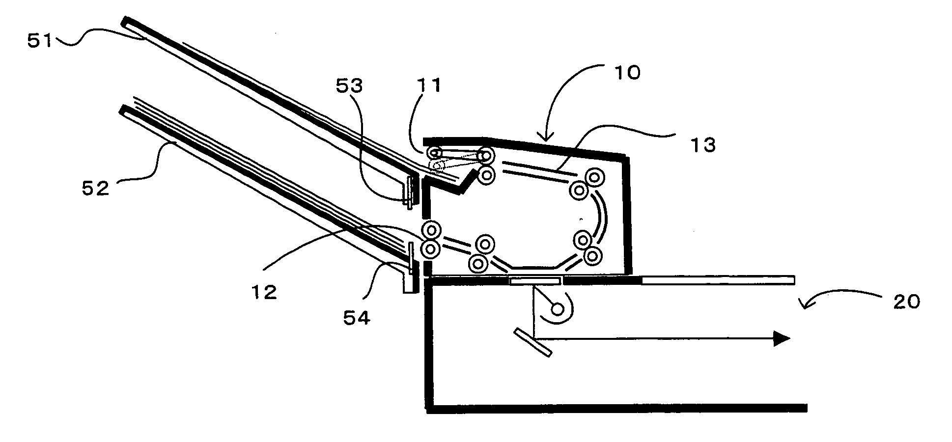
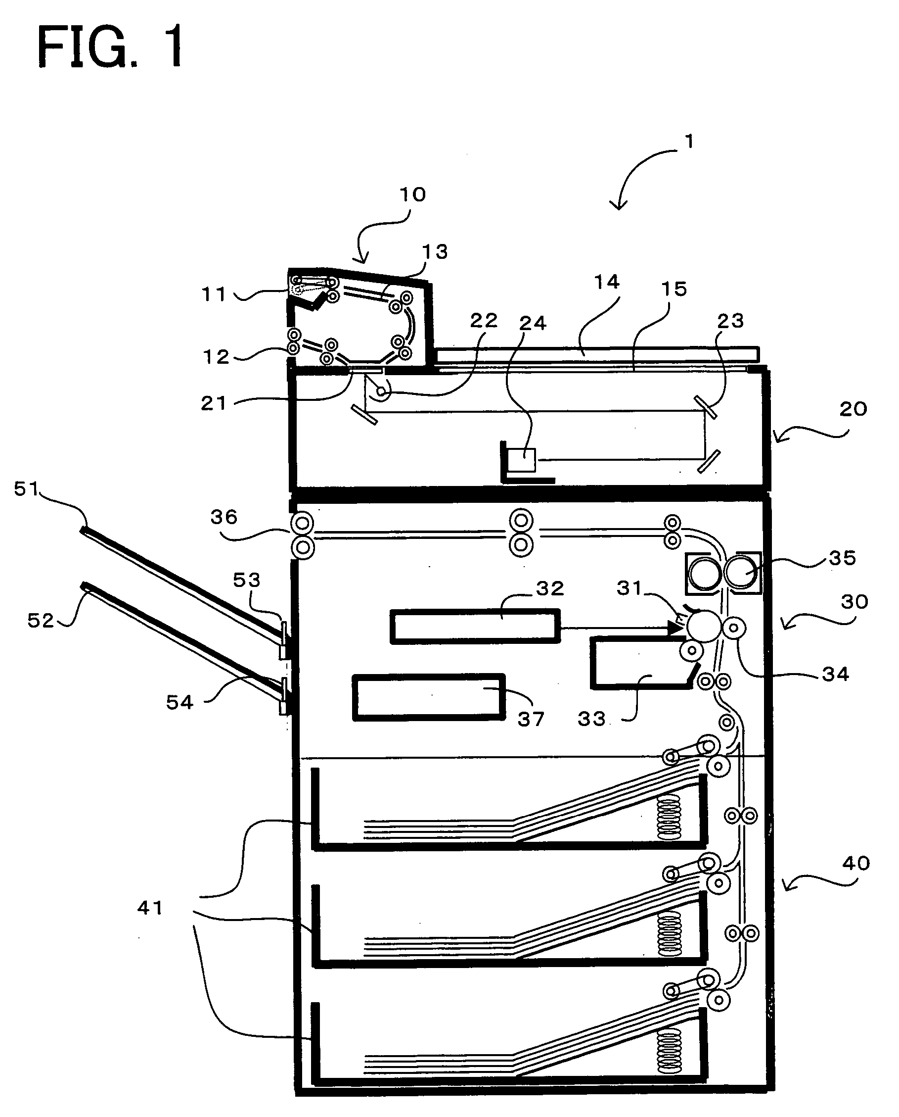
[0034] An image copying apparatus 1 of this embodiment comprises, as is schematically shown in FIG. 1, a document feeding section 10, a document reading section 20, an image forming section 30, and a sheet supplying section 40 in this order from above. The document feeding section 10 feeds original documents one by one from a drawing-in port 11 located at an upper side in FIG. 1 to a discharging port 12 located below the drawing-in port 11 through a document feeding path 13. The document feeding path 13 is folded in the midway into the shape of “U” letter, and faces a reading position 21 of the document reading section 20 at the downstream of the folded portion. Due to this form, the reading operation is performed while the original document being fed, that is, reading while being fed is performed. The image copying apparatus 1 further comprises a document cover 14 and a document glass 15, and is capable of reading operation for an original placed in a flat posture ...

Example

Second Embodiment

[0060] Next, a second embodiment embodying the present invention will be described in detail with reference the accompanied drawings. This embodiment describes an image copying apparatus including three or more of the movable trays of the first embodiment. The constituent elements identical to those of the first embodiments are denoted by the same reference numerals, and their description will be omitted.

[0061] An image copying apparatus 2 of this embodiment comprises a larger number of movable trays than the image copying apparatus 1 of the first embodiment. For example, as shown in FIG. 10, the image copying apparatus 2 of this embodiment comprises three movable trays 81, 81, 81. Each movable tray 81 is in the same structure as of the movable trays 51, 52 of the first embodiment. Due to this structure, as shown in FIG. 10, reading and discharging the original documents can be performed by use of two movable trays 81, 81. During executing these operations, sheets...

Example

Third Embodiment

[0066] Next, a third embodiment embodying the present invention will be described in detail with reference to the accompanied drawings. This embodiment describes an image copying apparatus having a fixed tray besides the movable trays of the first embodiment. The constituent elements identical to those of the first embodiments are denoted by the same reference numerals, and their description will be omitted.

[0067] An image copying apparatus 3 of this embodiment comprises, as shown in FIGS. 12 and 13, one fixed tray 85 adding to the trays of the image copying apparatus 1 of the first embodiment. The fixed tray 85 is fixed at a relatively low position at a height of about 30 to 50 cm from the floor level. The fixed tray 85 is used for placing sheets carrying formed images. Therefore, the fixed tray 85 is located next to the sheet discharging port 36.

[0068] Since there is no need to move the fixed tray 85, the fixed tray 85 may be relatively heavy in weight. Therefor...


PUM


Abstract

The image copying apparatus of the present invention comprises a document drawing-in port for drawing an original document before reading operation in and a document discharging port for discharging the original document after reading operation, and copies images of the original document on a medium. The image copying apparatus further comprises trays more than two which are movable upward and downward within a range covering a document feeding position to the document drawing-in port, a receiving position from the document discharging port, and a bottom region located further lower than the lower of these positions. At least one of the trays moves to a position within the bottom region, a tray on which an original document is placed moves to a document feeding position, and another tray moves to a document receiving position.

Description

[0001] This application is based on Application No. 2004-277873 filed in Japan, contents of which are hereby incorporated by reference. BACKGROUND OF THE INVENTION [0002] 1. Field of the Invention [0003] The present invention relates to an image copying apparatus and an image copying method for reading images on an original document and copying the images on a sheet. More specifically, the present invention relates to the image copying apparatus including an automatic document feeding device, and an image copying method in the image copying apparatus. [0004] 2. Description of the Related Art [0005] In recent years, universal designs aiming to embody products easy for any people to use have been adopted. In this circumstance, an image copying apparatus including an automatic document feeding device is also desired to incorporate universal designs. Conventionally, in the image copying apparatus, a document reading device is located at the uppermost portion of the image copying apparat...

Claims


Application Information

Patent Timeline
IPC IPC(8): G03G15/00
CPCG03G15/605G03G2215/00928G03G15/6552
Inventor SHIBATA, YOSHIFUMIKAGAWA, TETSUYAKUROYANAGI, YUICHI
Owner KONICA MINOLTA INC
Why Eureka
Try Eureka