Smart valved holding chamber
- Summary
- Abstract
- Description
- Claims
- Application Information
AI Technical Summary
Benefits of technology
Problems solved by technology
Method used
Image

Examples
Example
[0149]A microphone is placed in a similar spot as in embodiment 4.1.1. As shown in FIGS. 58 and 59A-B, a vibrating reed 115 or reeds 84, edge tones or flow over an open or closed tube may be used to generate sound as flow passes over and this volume should be substantially larger than those present in the chamber itself. The microphone 82 communicates with the computer 500 and processor 502.
4.2. Low Pass, High Pass and Band Pass Filter Volume Based
[0150]As mentioned in embodiment 4.1.1., volume based methods may be vulnerable to false readings due to ambient noise. To reduce this risk, digital and / or analog filtering may be implemented so that the system is only effectively “listening” to particular frequency bands. These filters would be selected such that the sounds intrinsic to the chamber are listened to or in the case of the sound generation, these frequencies are monitored.
4.3. Algorithm Based
[0151]The sounds coming from the chamber at different flow rates, whether these sound...
Example
[0176]Using the forces generated by flow as described in embodiment 9.1., a vane may be designed such that it adjusts a potentiometer when flow is present. A biasing spring will make the position of the vane dependent on the flow present. The resistance of the potentiometer may be monitored continuously and the flow inferred based on this measurement.
MDI Actuation Detection
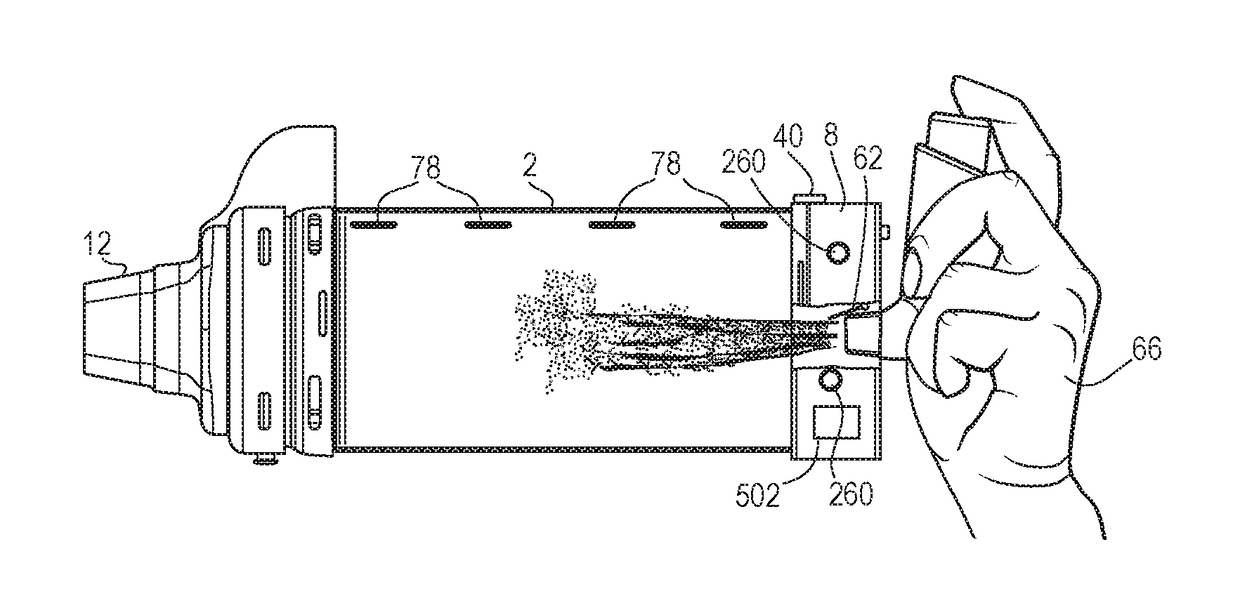
[0177]Detection of MDI actuation is an important piece of information that can be used for dose assurance and for providing feedback to the user about optimizing their breathing technique. Several characteristics of the MDI can be used and detected by an actuation detector, as described in various embodiments below, to detect the MDI actuation including the visual appearance of the aerosol plume, its sound, the temperature drop associated with rapid HEA propellant evaporation, its force to fire, the dielectric constant of the aerosol, displacement to fire, its pressure at actuation or communications with smart fea...
Example
[0210]Similar to embodiment 1.1, and referring to FIG. 74, a portion 200 of the MDI is magnetized either with magnetic ink, electromagnets or permanent magnets. When the MDI is inserted, a reed switch 202 is closed. The closing and opening of this switch have identical consequences for microcontroller operation and user feedback as described in 1.1.
1.3. Conductive Path
[0211]In this embodiment, as shown in FIG. 75, a portion of the MDI, for example the mouthpiece, has an electrically conductive path 204 which, when inserted into the MDI adapter, completes a circuit 206 within the MDI adapter electronics. This circuit is used to provide feedback to the user and enable full functionality of the microcontroller as described in 1.1.
2. Light Curtain
[0212]A light curtain, as disclosed previously, may be used to determine insertion of the MDI into the MDI adapter. In this embodiment, an LED and photodiode are placed opposite each other across the MDI adapter opening. When no MDI is inserted...
PUM
 Abstract
Description
Claims
Application Information
 - R&D Engineer
- R&D Manager
- IP Professional
- Industry Leading Data Capabilities
- Powerful AI technology
- Patent DNA Extraction
Browse by: Latest US Patents, China's latest patents, Technical Efficacy Thesaurus, Application Domain, Technology Topic.
© 2024 PatSnap. All rights reserved.Legal|Privacy policy|Modern Slavery Act Transparency Statement|Sitemap