
Capacitive keyboard

a capacitive keyboard and keyboard technology, applied in the direction of keyboard-like device coding, pulse technique, coding, etc., can solve the problems of inability to detect exact voltage, voltage value might not reach a threshold, detection might fail, etc., and achieve high accuracy

Inactive Publication Date: 2017-11-23
TOPRE
View PDF6 Cites 0 Cited by
  • Summary
  • Abstract
  • Description
  • Claims
  • Application Information

AI Technical Summary

Benefits of technology

The present invention is a capacitive keyboard that can detect the pressure of a keys pressed by an operator with high accuracy. The keyboard has a sensing circuit that detects the voltage generated in a sensing line when the key is pressed. This voltage is then held by a peak hold unit and converted into a multi-stage digital voltage value. This value is used to detect the specific key and the amount of pressure applied by the operator. Overall, the invention allows for more precise and accurate detection of keys pressed on a capacitive keyboard.

Problems solved by technology

However, if a key other than the key 103a is depressed as a result of erroneously or intentionally depressing a plurality of keys, for example, the sensing circuit 102 cannot detect the exact voltage in some cases.
Accordingly, the voltage value might not reach a threshold for determining whether or not the key has been depressed, and the detection might fail.
If three or more keys are depressed at the same time, such detection failure may occur with a higher possibility.
Although the technique disclosed in PTL 1 can detect whether or not a key has been depressed, it is difficult to detect the depressed amount of the key.
In addition, if a plurality of keys are depressed at the same time, a problem arises in that the depressed amount of each key cannot be detected with high accuracy.

Method used


Image

  • Capacitive keyboard
  • Capacitive keyboard
  • Capacitive keyboard

Examples


Embodiment Construction

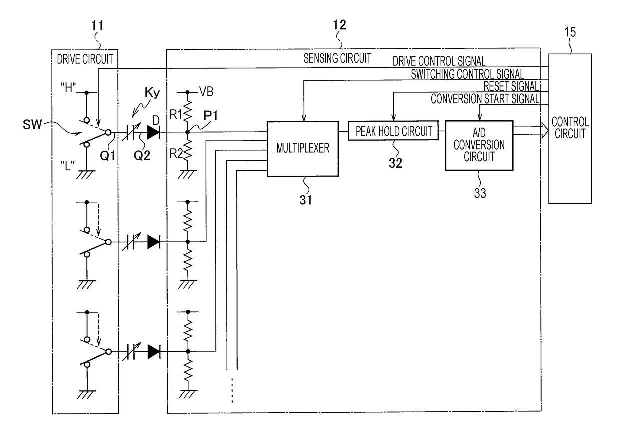
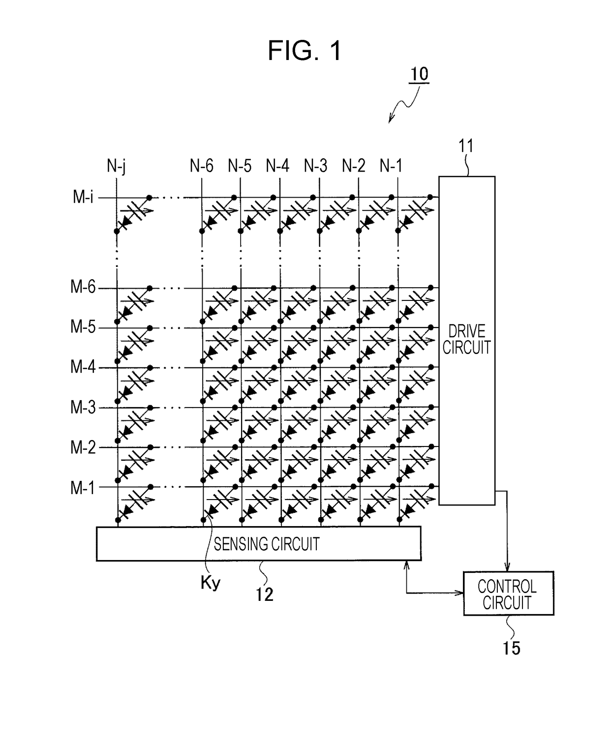
[0024]Now, an embodiment of the present invention will be described below with reference to the drawings. FIG. 1 schematically illustrates the configuration of a capacitive keyboard device according to the embodiment of the present invention. As illustrated in FIG. 1, in a capacitive keyboard 10 according to this embodiment, a plurality (for example, the number being i) of drive lines M (M-1, M-2, M-3, . . . , M-i) and a plurality (for example, the number being j) of sensing lines N (N-1, N-2, N-3, . . . , N-j) are arranged to intersect (cross) one another. Note that in the following description, unless indicating a specific drive line, the drive lines are denoted by symbol “M”, and if indicating a specific drive line, the individual drive lines are denoted by a suffix such as “M-1”. Similarly for the sensing lines, unless indicating a specific sensing line, the sensing lines are denoted by symbol “N”, and if indicating a specific sensing line, the individual sensing lines are denot...


PUM


Abstract

A capacitive keyboard that can detect a key that has been depressed and the depressed amount thereof with high accuracy is provided. The capacitive keyboard includes a drive circuit 11 that alternatively switches the voltage of each of drive lines M from an L-level to an H-level, a sensing circuit 12 that detects the voltage generated in each of sensing lines N, and a control circuit 15 that detects, on the basis of the voltage value detected by the sensing circuit 12, the key that has been operated and the operation amount of the operated key. The sensing circuit 12 includes a peak hold circuit 32 that holds the peak value of the voltage that is input from a sensing line N over a predetermined period and an A / D conversion circuit 33 that converts the voltage held by the peak hold circuit 32 into a multi-stage digital voltage value.

Description

TECHNICAL FIELD[0001]The present invention relates to a capacitive keyboard including a plurality of capacitive keys arranged in a matrix.BACKGROUND ART[0002]As a keyboard used for a personal computer and the like, a capacitive keyboard including a plurality of capacitive keys has been proposed and put into practical use. A capacitive keyboard includes a plurality of drive lines and a plurality of sensing lines that intersect the drive lines, and a capacitive key is arranged at each of the intersections of the drive lines and the sensing lines. Upon depressing of any one of the plurality of keys, the capacitance between two electrodes of the key is increased, and accordingly, current flows from a corresponding one of the drive lines through the depressed key to a corresponding one of the sensing lines. By detecting the current, the depressed key can be recognized (see, for example, PTL 1).[0003]Now, a capacitive keyboard of the related art will be described below with reference to F...

Claims


Application Information

Patent Timeline
IPC IPC(8): H03K17/96H03M11/00H03M11/20
CPCH03K17/9622H03K2017/9613H03M11/003H03M11/20G06F3/0202G06F3/023G06F3/0445G06F3/0446H03K2217/94036
Inventor MINEZAKI, SHIGEKI
Owner TOPRE
Learn More