Tissue removal system
a tissue and system technology, applied in the field of tissue removal system, can solve the problems of small stress given to patients and limited lesion size resected,
- Summary
- Abstract
- Description
- Claims
- Application Information
AI Technical Summary
Benefits of technology
Problems solved by technology
Method used
Image
Examples
first embodiment
ystem
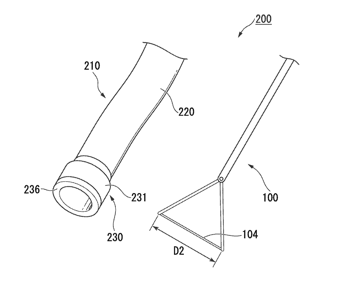
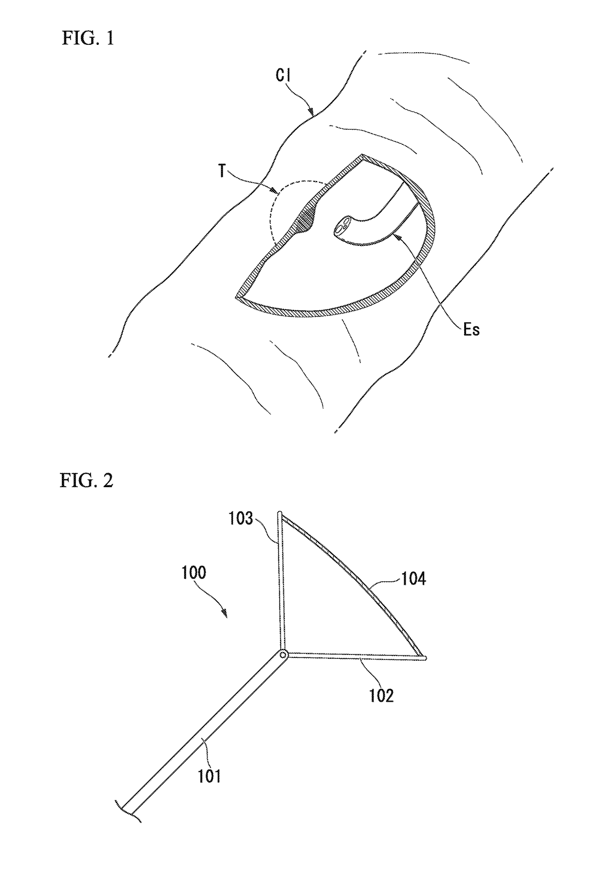
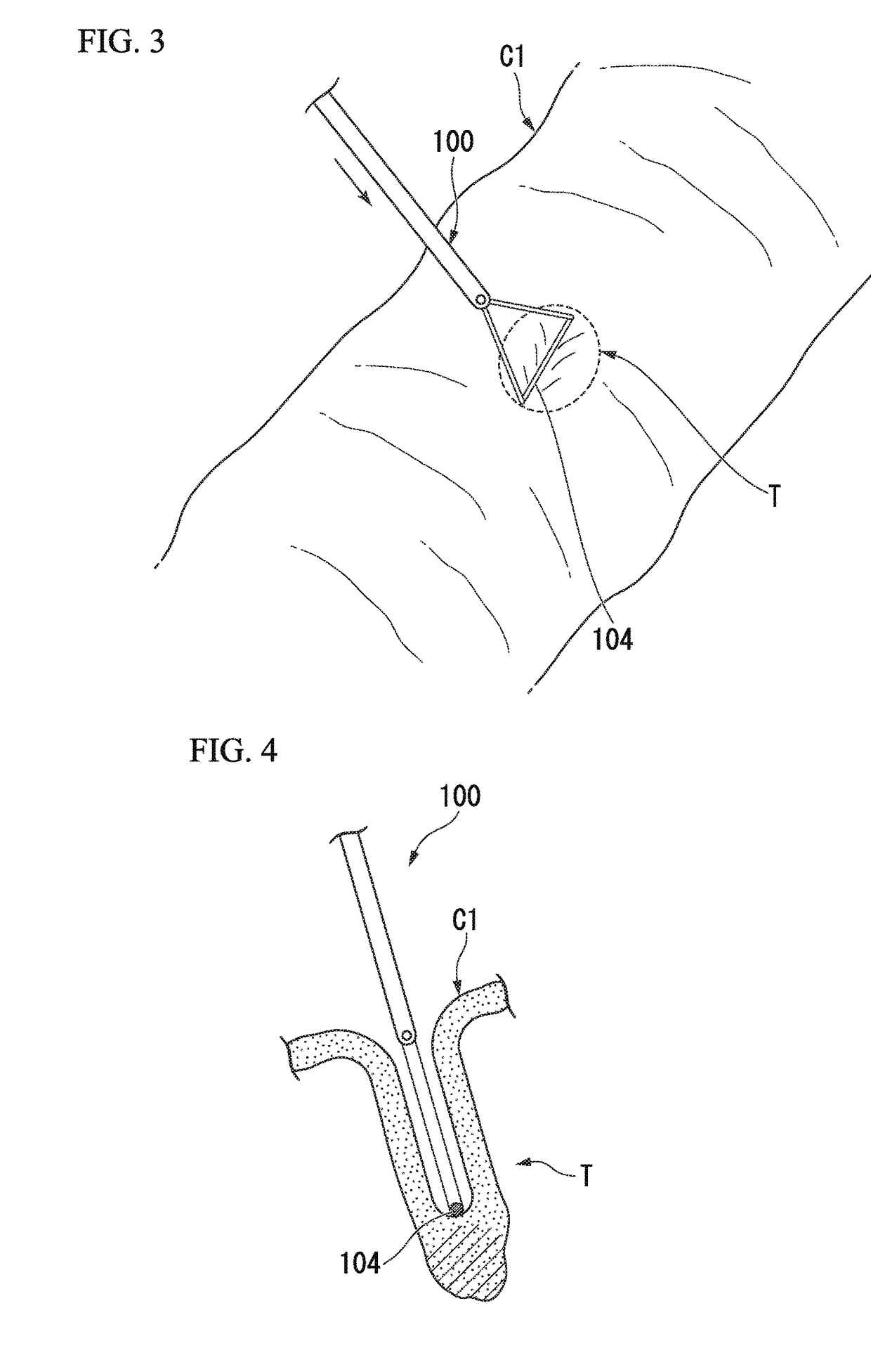
[0060]Next, a first embodiment of the invention will be described with reference to FIGS. 8 to 15. In the first embodiment, a tissue removal system that can suitably perform the tissue resection method described in the reference example will be described. In the subsequent description, the same components as those already described will be designated by the same reference signs and the redundant description thereof will be omitted.
[0061]FIG. 8 is a view illustrating a tissue removal system 200 related to the first embodiment. The tissue removal system 200 includes a tissue pressing tool and a resection and anastomosis device 210. Although various kinds of tissue pressing tools can be used in the tissue removal system 200, the tissue pressing tool 100 described in the above-described modification example is illustrated as an example in FIG. 8.
[0062]The resection and anastomosis device 210 related to the first embodiment will be described. The resection and anastomosis device 210...
second embodiment
[0080]A second embodiment of the invention will be described with reference to FIG. 16. FIG. 16 is a sectional view illustrating a distal end part of a treatment part of a resection and anastomosis device 250 in a tissue removal system related to the second embodiment, in the same aspect as that of FIG. 10. In the resection and anastomosis device 250, only one forward and backward movable shaft 252 connected to the anvil part (not illustrated) is provided. As illustrated in FIG. 16, the sectional shape of the forward and backward movable shaft 252 is formed in a substantial U-shape opening toward the central axis X1 of the main body 231, and the tissue abutment line L3 is defined by an end part 252a (the first tissue abutment part) and an end part 252b (the second tissue abutment part) of the forward and backward movable shaft 252 that are separated from each other in the substantial U-shape.
[0081]The tissue removal system using the resection and anastomosis device 250 including the...
third embodiment
[0083]A third embodiment of the invention will be described with reference to FIGS. 17 and 18. FIG. 17 is a partially enlarged view illustrating a distal end part of a resection and anastomosis device 260 in a tissue removal system related to the third embodiment. The resection and anastomosis device 260 includes the tubular insertion 220 that allows the endoscope to be inserted therethrough, a treatment part 261 provided at the distal end part of the insertion 220, and the operating part (not illustrated) provided at the proximal end part of the insertion 220. The insertion 220 has flexibility and functions as an overtube for introducing the endoscope into the hollow organ. The treatment part 261 includes the cylindrical main body (first member) 231 fixed to the insertion 220, and the annular anvil part (second member) 236 attached to the distal end side of the main body 231 so as to be capable of being brought close to and separated from the main body 231.
[0084]In the resection an...
PUM
 Abstract
Description
Claims
Application Information
 - R&D
- Intellectual Property
- Life Sciences
- Materials
- Tech Scout
- Unparalleled Data Quality
- Higher Quality Content
- 60% Fewer Hallucinations
Browse by: Latest US Patents, China's latest patents, Technical Efficacy Thesaurus, Application Domain, Technology Topic, Popular Technical Reports.
© 2025 PatSnap. All rights reserved.Legal|Privacy policy|Modern Slavery Act Transparency Statement|Sitemap|About US| Contact US: help@patsnap.com


