High Performance Free Rolling Cable Transmission

a transmission cable and high-performance technology, applied in the direction of prosthesis, manufacturing tools, gearing, etc., can solve the problems of limiting the size and flexibility of the system, poor control performance, and usually complex and bulky, and achieves low frictional force, efficient transmission of motion and mechanical power, and high efficiency

Inactive Publication Date: 2017-12-07
MASSACHUSETTS INST OF TECH
View PDF4 Cites 28 Cited by
  • Summary
  • Abstract
  • Description
  • Claims
  • Application Information

AI Technical Summary

Benefits of technology

[0013]This invention includes many advantages. For example, the mechanical transmission, the tethered actuation system of the invention, and the method of the invention can efficiently transmit motion and mechanical power from an input device, such as a motor, to an output device, or end-effector, via a cable or its equivalent, such as a rope. With a high level of efficiency and minimal frictional forces in the transmission, angular transmission of linear force on the cable or rope can be effected without physical constraints on the location of the output relative to the input in three-dimensional space. Since the mechanical transmission significantly reduces friction resistance and significantly reduces cable slackness, independent of the location of the output relative to the input, it is highly backdrivable. Specifically, an embodiment of the mechanical transmission of the invention is compact, modular, lightweight, stiff, highly backdrivable and free to rotate in three-dimensional space with virtually zero backlash between the transmission's input and the output. Since the mechanical transmission of the invention is compact and modular, and since it can be used for both bidirectional and unidirectional actuation, it is use

Problems solved by technology

Compared with other mechanical power transmissions, such as linkages and gears, cables are relatively lightweight and flexible but may suffer from friction losses and cable slackness, leading to poor control performance.
However, such devices are usually complex and bulky, limiting the size and flexibility of the systems.
This can introduce compliance to the systems, deteriorating the efficacy of the devices.
However, cable housings or frames of these devices using multiple pulleys must be specifically designed and are usually bulky, limiting the size and flexibility of the systems, and inevitably leading to a difficulty in use in different forms.
They are now also frequently used with wearable devices, such as described in [9], [8], because they are lightweight and flexible, and because human mo

Method used


Image

  • High Performance Free Rolling Cable Transmission
  • High Performance Free Rolling Cable Transmission
  • High Performance Free Rolling Cable Transmission

Examples


embodiment 1400

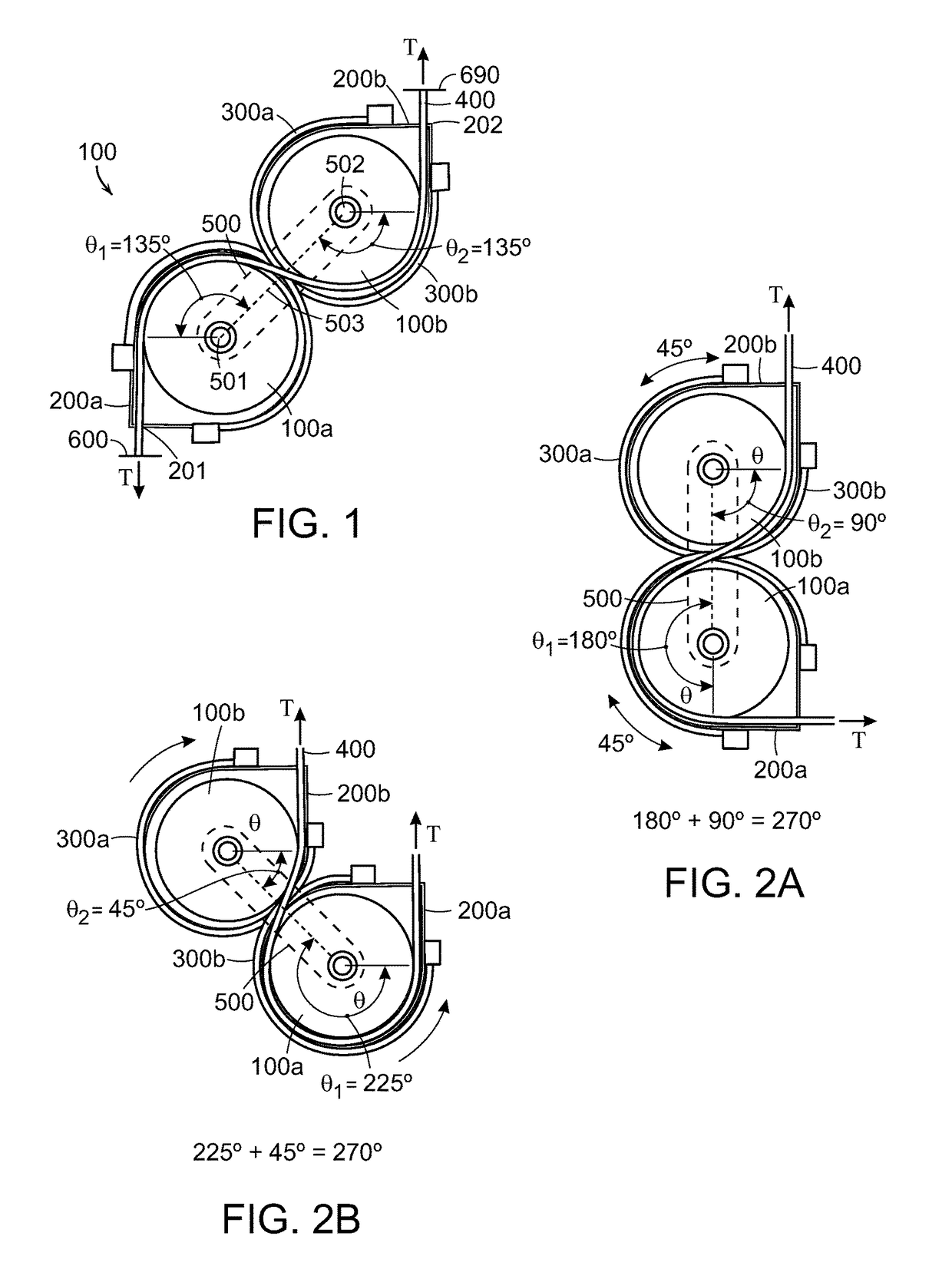
[0040]When inner cable 400 is under tension T, it tends to push two pulleys 100a, 100b away from each other, rotating the whole transmission mechanism. However, agonist and antagonist tendons 300a, 300b and external cable housings contribute to the resultant reaction force on each housing 200a and 200b, balancing the resultant force on the associated pulleys 100a and 100b, respectively. Therefore, the total sum of forces, except the weight, on rotating arm 500, is always zero. Accordingly, even if inner cable 400 is under great tension, transmission mechanism 100 is free to rotate and thus free to translate. Agonist and antagonist tendons 300a, 300b can be substituted with alternative coupling components that keep a 1:1 angular velocity ratio between two pulley housings 200a, 200b, such as a pair of gears, belts, linkages, etc. (See, e.g., gears 19 of FIGS. 3-6). Moreover, the angular velocity ratio between two pulley housings 200a, 200b can be other than 1:1, such as that the radiu...

first embodiment

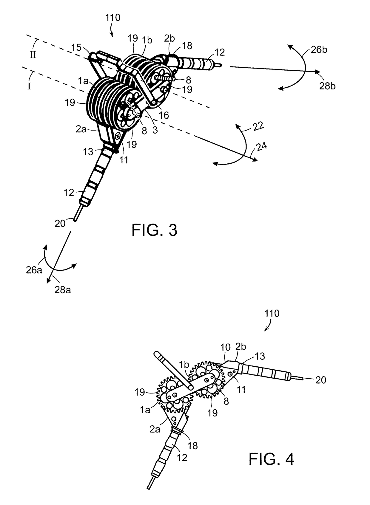
[0056]Cable housings 612 are attached to pulley housings 602a, 602b by adapters 613 and C-clips 610. Thrust bushings 618 between cable housings 612 and pulley housing 602a, 602benable cable housings 612 to rotate with respect to the pulley housings 602a, 602b about an axis orthogonal to the centers of rotation of the pulley housings. Accordingly, transmission 120 is free to rotate in three-dimensional space, in the same way as the first embodiment shown in FIG. 3.

[0057]Pulleys 601a, 601b are free to rotate with respect to the associated pulley housings 602a, 602b but are driven by inner cable 620. From the input end through one cable housing 612, inner cable 620 wraps around one of two pulleys 601a, 601b, crosses the line of the centers of pulleys 601a, 601b, and then wraps around the other pulley 601 in the opposite direction, going to the output end through the other cable housing 612. Inner cable 620 can transmit motion and power from the input to the output, driving the pulleys ...


PUM


Abstract

A mechanical transmission, tethered actuation system, an autonomous ankle exoskeleton design and method of their use employing a cable, pulleys and associated pulley housings to change angular transmission of linear force on the cable. The pulleys are linked by a ground link and the cable is threaded across and between the pulleys, whereby rotation of either of the pulleys in one direction causes rotation of the other pulley in the opposite direction. Independently of the pulleys, the pulley housings can freely rotate about associated pulleys, and a link between the pulley housings is provided, whereby rotation of one of the pulley housings in one direction causes rotation of the other pulley housing at an equivalent angle in the opposite direction, thereby enabling a change in transmission angle of linear force on the cable threaded across and between the pulleys and the associated pulley housing essentially without resistance. When pulleys have the same angular velocity ratio as that of the associated pulley housings, there is no cable slack since the net changes in length of the cable wrapping around two pulleys is zero.

Description

RELATED APPLICATION[0001]This application claims the benefit of U.S. Provisional Application No. 62 / 344,635, filed on Jun. 2, 2016. The entire teachings of the above application are incorporated herein by reference.GOVERNMENT SUPPORT[0002]This invention was made with government support under Grant No. NNX12AM16G from the National Aeronautics and Space Administration. The government has certain rights in the invention.BACKGROUND[0003]Cables have long been regarded as one of the most flexible ways to transmit mechanical power and motion, especially, for long-distance actuation where the motor input is spatially separated from the output end effector. A non-exhaustive list of common cable driven devices include wearable robotic emulator devices for prosthetic, orthotic and exoskeletal devices; robotic therapy tools, robotic surgical tools, bicycle brakes, dental drills, hair shearing, and cranes. In order to transmit mechanical power and motion from an input to an output, cable housing...

Claims


Application Information

Patent Timeline
IPC IPC(8): A61H3/00A61F2/66F16H19/00A61F2/50
CPCA61H3/00F16H19/005A61F2002/503A61F2002/5038A61F2/6607A61H1/0237A61H2201/1215A61H2201/1418A61H2201/1436A61H2201/1642A61H2201/165B25J9/0006B25J9/102B25J9/104F16H35/18
Inventor HERR, HUGH M.KUAN, JIUN-YIH
Owner MASSACHUSETTS INST OF TECH
Why Eureka
Try Eureka