Spring bed device with heating function

a technology of a spring bed and a function, which is applied in the direction of fluid mattresses, heating types, lighting and heating apparatus, etc., can solve the problems of hot air generation, damage to the heating line, and too hard to satisfy the user who seeks comfort, etc., and achieve the effect of convenient operation of the operation button

Active Publication Date: 2017-12-07
YOO SENG YEUL +1
View PDF21 Cites 16 Cited by
  • Summary
  • Abstract
  • Description
  • Claims
  • Application Information

AI Technical Summary

Benefits of technology

[0025]First, according to the spring bed device with heating function according to the present invention, the two hot-air guide members may be symmetrically disposed about the hot-air discharge tube, wherein the two air guide members are configured to guide the hot-air such that the hot air discharged from the hot-air discharge tube is distributed uniformly over an entire area of the spring mattress. In this way, this allows hot-air and heat to be supplied throughout the surface of the spring mattress, like a traditional heated flat stone system.
[0026]In addition, according to the spring bed device with heating function according to the present invention, the air sucked through the air intake holes is dehumidified. Thus, the hot-air circulating in the spring mattress can be kept in an optimal state.
[0027]Further, according to the spring bed device with heating function according to the present invention, the pair of blowing fans is provided for hot-air supply. This prevents vortices between the heater and the blowing fans, and maintains the heated hot air at a constant temperature.
[0029]Finally, according to the spring bed device with heating function according to the present invention, by providing the LED module in the remote control unit, the user can easily operate the operation button without a separate illumination device even when sleeping at night.

Problems solved by technology

In this case, the soft cushion of the bed device could cause deformation of the electric mattress, resulting in damage to its heating line.
It is too hard to satisfy the user who seeks comfort.
There is also a disadvantage that only hot air is generated.
However, in this bed device of the prior art, the heating air blown from the hot air generation device does not concentrate on the upper shell of the spring mattress, but leaks to the front, rear, side and lower faces thereof.
Therefore, it takes a long time to warm up the spring mattress.
Also, since the hot air generation device is to be operated for a long time so that the spring mattress becomes warm, the thermal efficiency is low and it is not economical.
Therefore, there was a problem that it was not possible to maintain almost the same temperature throughout the spring mattress.
In addition, when the user uses the spring mattress shown in FIG. 1, there is a problem that hot air is delivered only at the user's head and warm air is not transmitted to the waist.
However, this has a problem in that temperature control cannot be performed sequentially and the temperature cannot be kept constant throughout the spring mattress.
In the above-described Patent Document 3, although the ventilating screen is provided at the central portion of the spring mattress, since the air inlet and the air outlet are provided on both sides of the front portion of the spring mattress respectively, the temperature cannot be controlled uniformly throughout the spring mattress.
In other words, the temperature of the air inlet portion becomes higher, but the temperature of the portion of the air outlet is lowered so that the temperature cannot be controlled uniformly throughout the spring mattress.

Method used


Image

  • Spring bed device with heating function
  • Spring bed device with heating function
  • Spring bed device with heating function

Examples


Embodiment Construction

[0040]These and other objects and novel features of the present invention will become more apparent from the description of the present specification and the accompanying drawings.

[0041]Spatially relative terms, such as “beneath,”“below,”“lower,”“under,”“above,”“upper,” and the like, may be used herein for ease of explanation to describe one element or feature's relationship to another element or feature as illustrated in the figures.

[0042]For example, if the device in the figures is turned over, elements described as “below” or “beneath” or “under” other elements or features would then be oriented “above” the other elements or features. It will be understood that the spatially relative terms are intended to encompass different orientations of the device in use or in operation, in addition to the orientation depicted in the figures.

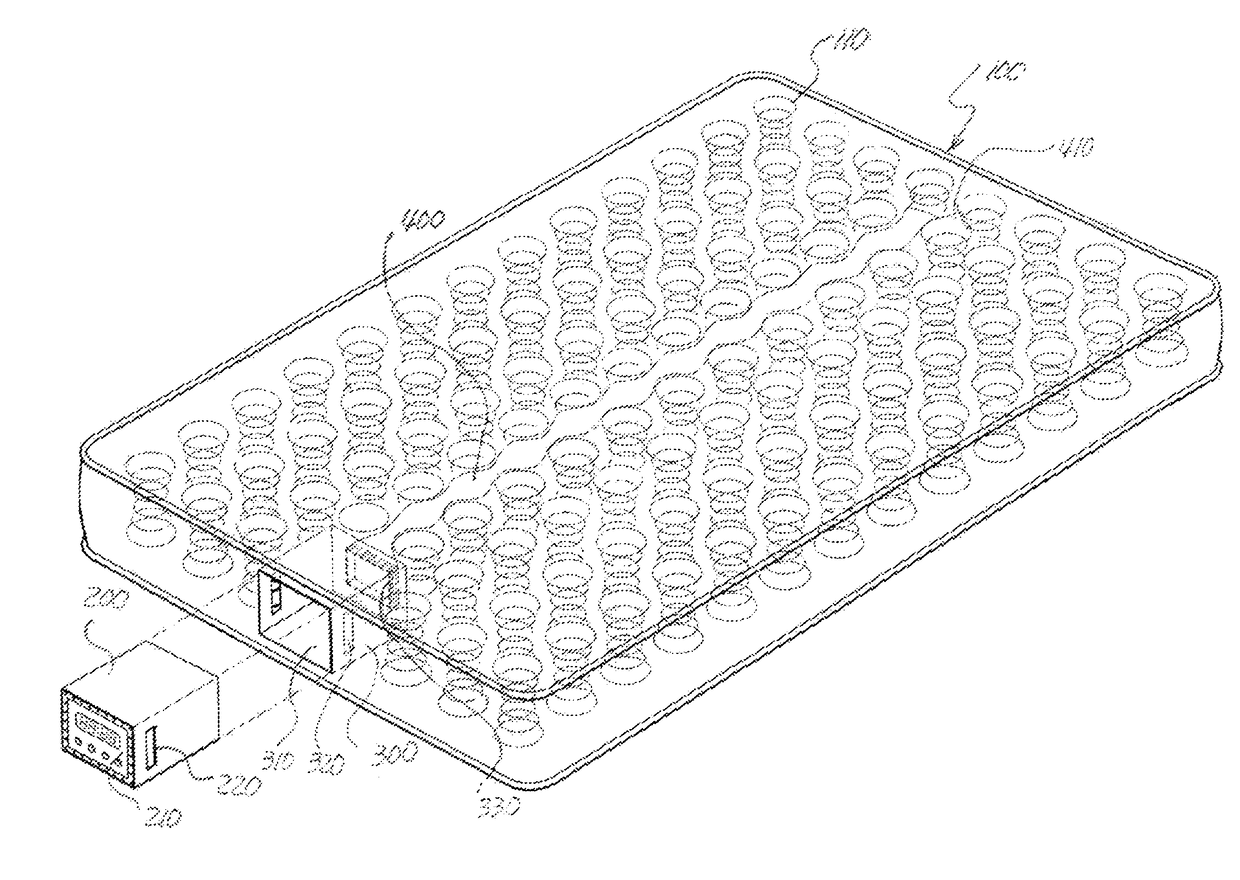
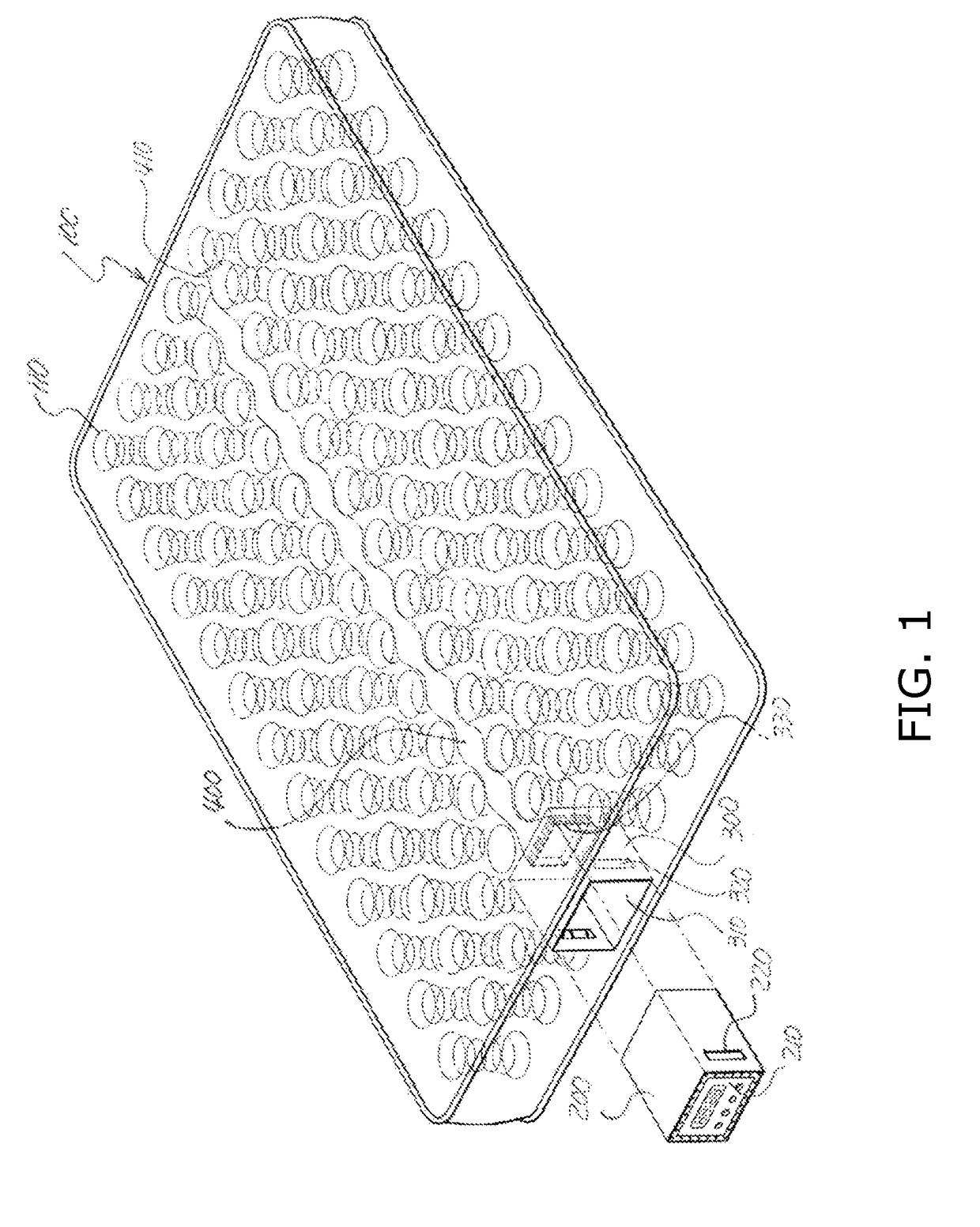
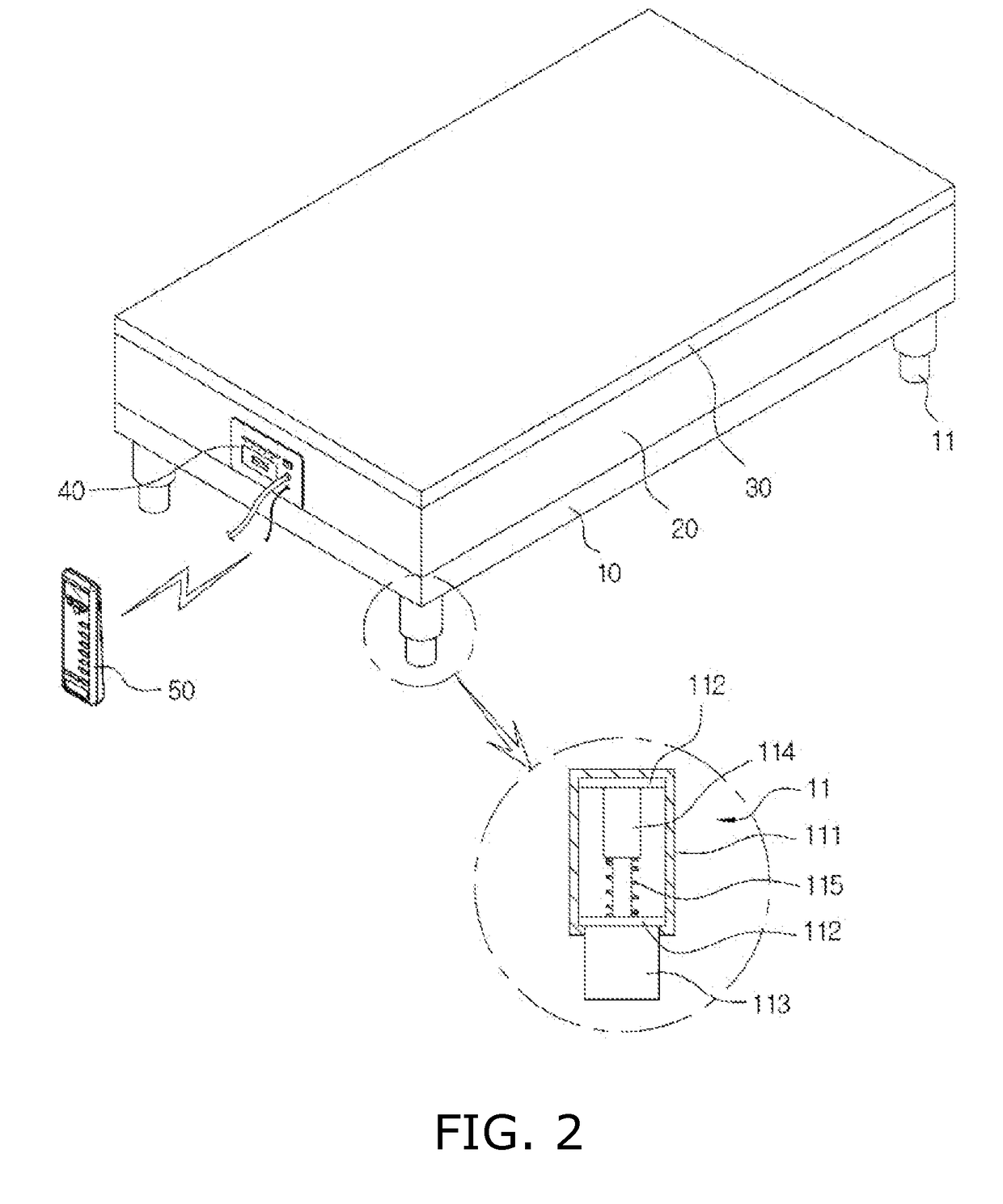
[0043]Hereinafter, the configuration of the present invention will be described with reference to the drawings.

[0044]FIG. 2 is a perspective view of the ...


PUM


Abstract

There is provided a bed device comprising: a support plate; a spring mattress provided on the support plate; a mat provided on the spring mattress; and a hot-air supply device for supplying hot air into the spring mattress, wherein the hot-air supply device is received in the spring mattress, wherein the hot-air supply device includes: a hot-air generation unit for generating hot-air; a hot-air discharge tube protruding from the hot-air generation unit by a predetermined length to discharge the hot-air generated in the hot-air generation unit into the spring mattress; and two hot-air guide members symmetrically disposed about the hot-air discharge tube, wherein the two air guide members are configured to guide the hot-air such that the hot air discharged from the hot-air discharge tube is distributed uniformly over an entire area of the spring mattress.

Description

BACKGROUNDField of the Present Disclosure[0001]The present invention relates to a spring bed device with a heating function, and more particularly to a spring bed device including a spring mattress with hot air heating function and massage function.Discussion of Related Art[0002]In general, the spring mattress used in the bed device has no heating or cooling function, so there have been efforts to add heating or cooling functions thereto.[0003]As part of that effort, a regular electric mattress is laid on the spring mattress, and a blanket is placed on it to add warmth. In this case, the soft cushion of the bed device could cause deformation of the electric mattress, resulting in damage to its heating line.[0004]In addition, the hot stone type bed device has been developed, which has a heating line embedded therein. This has the advantage of providing the same effect as the traditional hot stone type floor. It is too hard to satisfy the user who seeks comfort.[0005]On the other hand...

Claims


Application Information

Patent Timeline
Patent Type & Authority Applications(United States)
IPC IPC(8): A61H15/02A47C27/04A47C21/04A47C31/00
CPCA61H15/02A47C21/048A61H2201/5082A47C31/008A61H2201/5023A47C27/04A47C21/04A47C27/00F24D5/06A61H15/00A61H2201/0207A61H2201/025A61H2201/0146A47C27/08A47C27/10
Inventor YOO, SENG YEULYOU, JI HYUN
Owner YOO SENG YEUL
Why Eureka
Try Eureka