Fuel-injection device

Active Publication Date: 2017-12-07
ROBERT BOSCH GMBH
View PDF9 Cites 9 Cited by
  • Summary
  • Abstract
  • Description
  • Claims
  • Application Information

AI Technical Summary

Benefits of technology

[0010]The decoupling element is characterized by low height, which allows for its usage in small spaces as well. In addition, the decoupling element has considerable dynamic strength even at high temperatures. The decoupling element is able to b

Problems solved by technology

However, this type of noise damping is very reso

Method used


Image

  • Fuel-injection device
  • Fuel-injection device
  • Fuel-injection device

Examples


Embodiment Construction

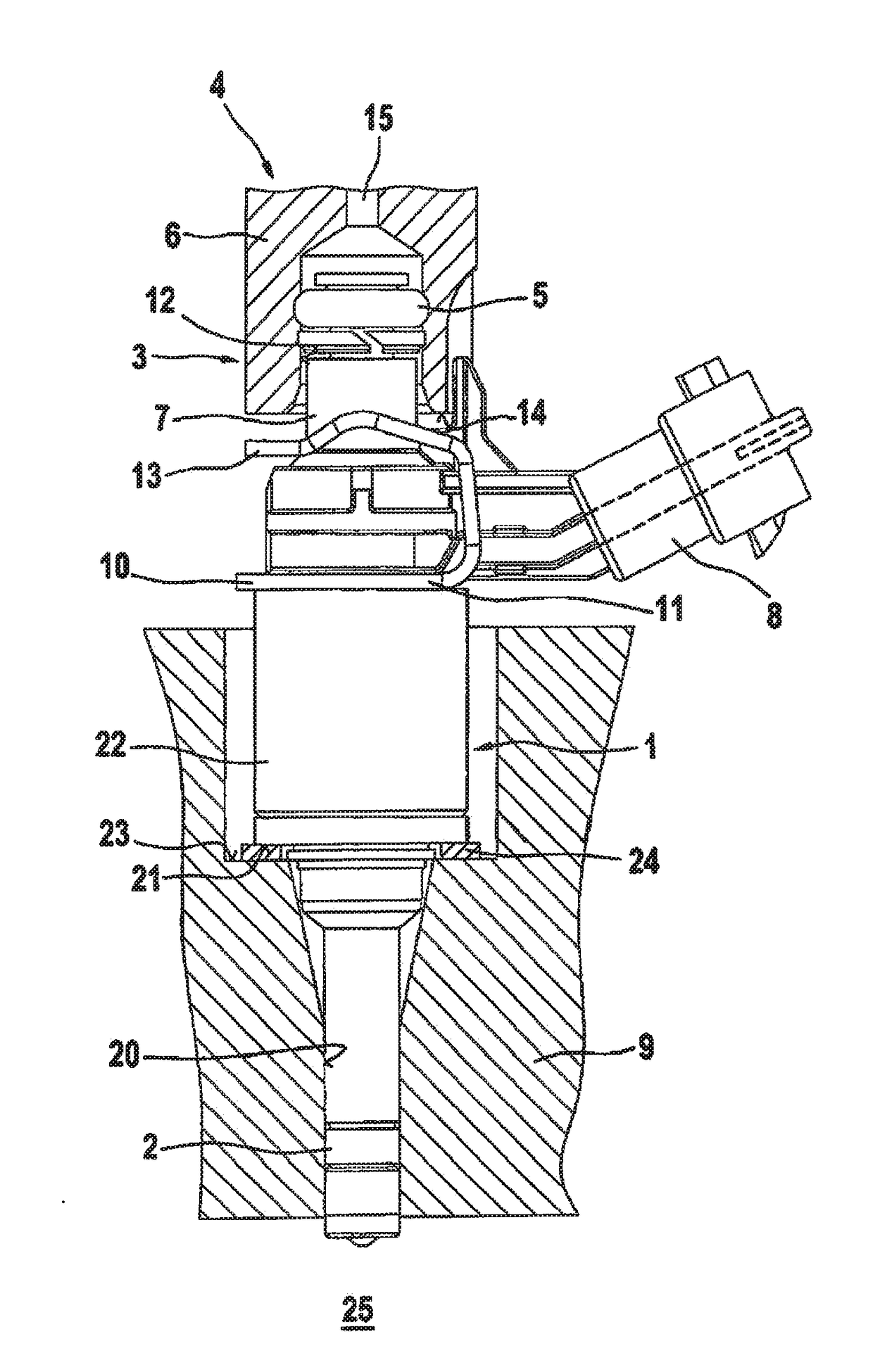
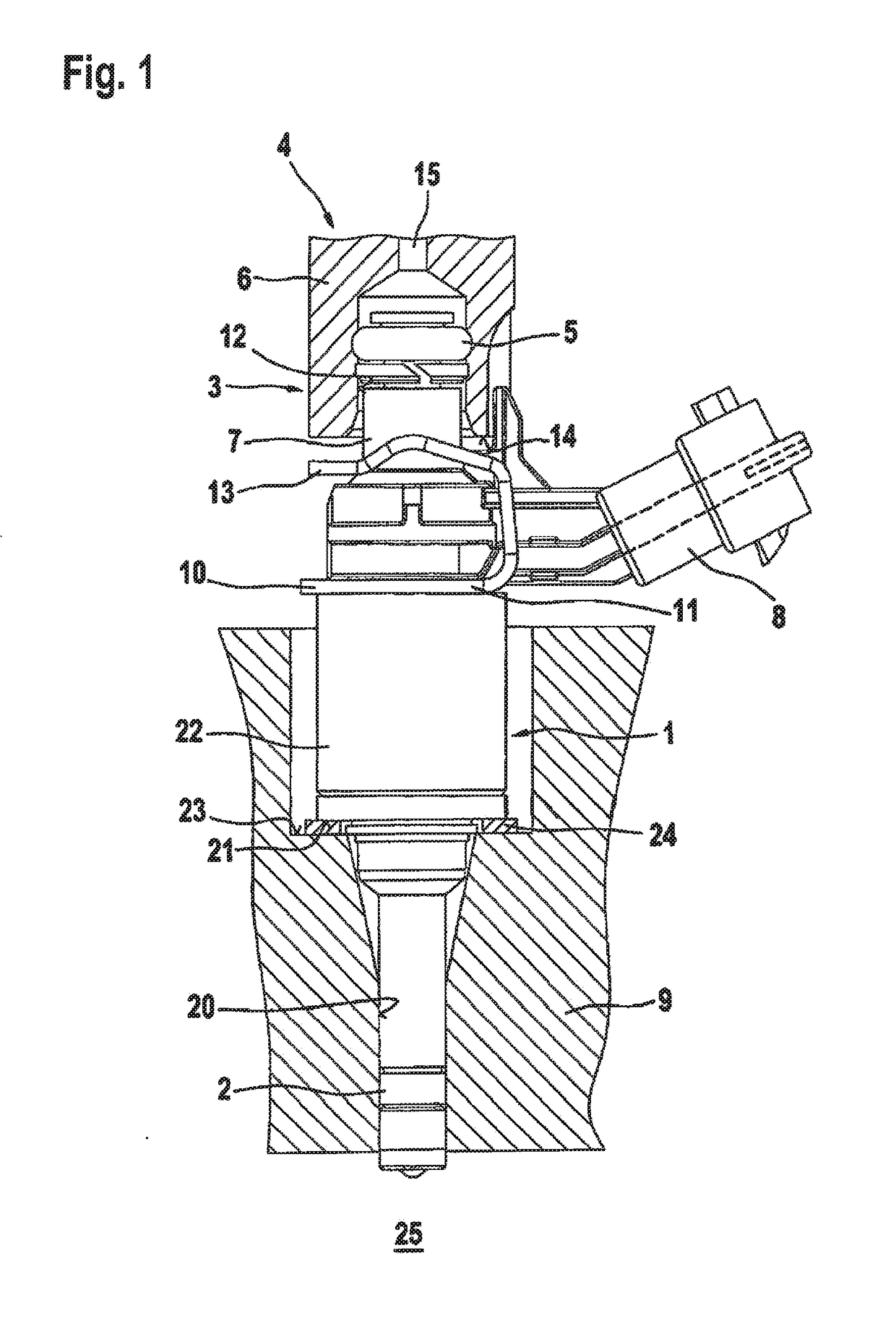
[0019]For an understanding of the present invention, a conventional specific embodiment of a fuel-injection device is described in greater detail in the following text on the basis of FIG. 1. FIG. 1 shows a valve in the form of an injector 1 for fuel-injection systems of mixture-compressing internal combustion engines having externally supplied ignition, as an exemplary embodiment in a side view. Fuel injector 1 is part of the fuel-injection device. By a downstream end, fuel injector 1, which is implemented in the form of a directly injecting injector for the direct injection of fuel into a combustion chamber 25 of the internal combustion engine, is installed in a receiving bore 20 of a cylinder head 9. A sealing ring 2, in particular made from Teflon®, provides optimum sealing of fuel injector 1 from the wall of receiving bore 20 of cylinder head 9.

[0020]A flat intermediate element 24, which is implemented as a bracing element in the form of a washer, is inserted between a step 21 ...


PUM


Abstract

A fuel-injection device has a low-noise and pivotable structure. The fuel-injection device includes at least a fuel injector and a receiving bore in a cylinder head for the fuel-injector, and a decoupling element between a valve housing of the fuel injector and a wall of the receiving bore. The decoupling element is captively situated on the fuel injector prior to its installation in the receiving bore in that a securing ring is mounted below the decoupling element at the outer periphery of the fuel injector and the securing ring is a closed plastic ring. The fuel-injection device is particularly suited for the direct injection of fuel into a combustion chamber of a mixture-compressing internal combustion engine having externally supplied ignition.

Description

FIELD[0001]The present invention is based on a fuel-injection device.BACKGROUND INFORMATION[0002]FIG. 1 shows a conventional fuel-injection device by way of example. Here, a flat intermediate element is provided on a fuel-injection valve installed in a receiving bore of a cylinder head of an internal combustion engine. In the known manner, such intermediate elements are placed as support elements in the form of washers on a shoulder of the receiving bore of the cylinder head. Intermediate elements of this kind are meant to compensate for production and installation tolerances and to ensure that transverse forces will not affect the mounting even when the fuel injector is positioned at a slight tilt. The fuel-injection device is especially suitable for use in fuel-injection systems of mixture-compressing internal combustion engines having externally supplied ignition.[0003]Another type of simple intermediate element for a fuel-injection device is described in German Patent Applicatio...

Claims


Application Information

Patent Timeline
IPC IPC(8): F02M61/14F02M61/16
CPCF02M61/168F02M61/14F02M2200/858
Inventor BAYER, JOHANNREINHARDT, WILHELM
Owner ROBERT BOSCH GMBH
Why Eureka
Try Eureka