Extended photovoltaic module fixture

a photovoltaic module and fixture technology, applied in the direction of photovoltaic supports, heat collector mountings/supports, light and heating apparatus, etc., can solve the problems of large installation area, inconvenient installation, and inability to manufacture power in a single fixture, so as to reduce the manufacturing cost of fixtures, reduce the occupied space, and increase economic efficiency and productivity

Inactive Publication Date: 2017-12-07
WANG CHANG GYUN
View PDF4 Cites 2 Cited by
  • Summary
  • Abstract
  • Description
  • Claims
  • Application Information

AI Technical Summary

Benefits of technology

[0013]According to the present invention, one side of an upper portion of a fixture is foldably connected to one end of a photovoltaic module, and simultaneously a photovoltaic module is slidably installed in the fixture, thus allowing a plurality of photovoltaic modules to be simultaneously installed in one fixture and to be extended if necessary, therefore facilitating conveyance and installation, minimizing an occupied space, reducing the manufacturing cost of the fixture, and consequently increasing economic efficiency and productivity.

Problems solved by technology

The photovoltaic generation has the following problems: a large installation area is required because of low energy density, and a space for installing a solar-cell panel should be secured because of a limited installation place.
In this case, a ship should be used to install the photovoltaic module in the water surface or perform maintenance, so that mobility is undesirably limited.
However, the photovoltaic module fixtures of Patent Document 1 and Patent Document 2 are problematic in that one photovoltaic module is fixed to one fixture unit, so that an occupied space is limited when a plurality of photovoltaic modules is installed, and an amount of produced power is limited in a single fixture.

Method used


Image

  • Extended photovoltaic module fixture
  • Extended photovoltaic module fixture
  • Extended photovoltaic module fixture

Examples


Embodiment Construction

[0023]Hereinafter, preferred embodiments of the present invention will be described in detail with reference to the accompanying drawings. However, since the embodiments merely aid in understanding the present invention, they are not intended to limit the present invention. A detailed description of technology that is obvious to those skilled in the art or is readily obtained will be omitted herein.

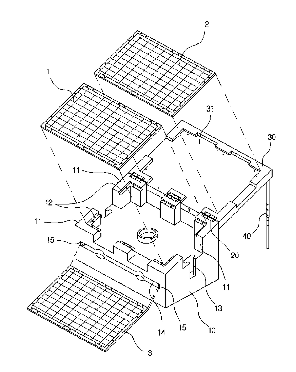
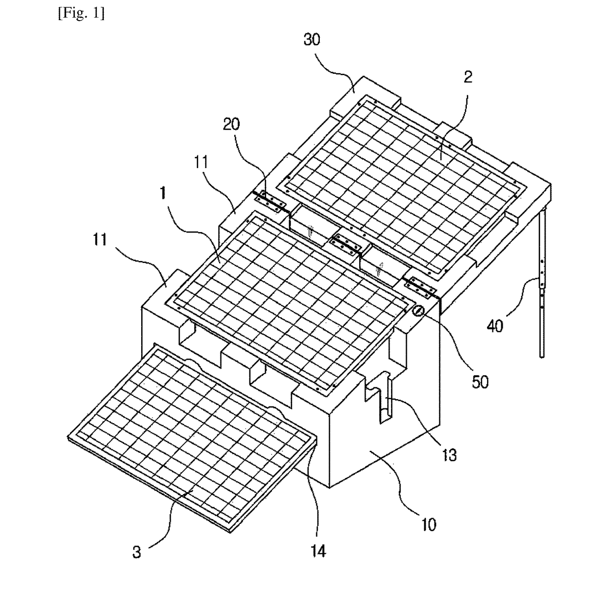
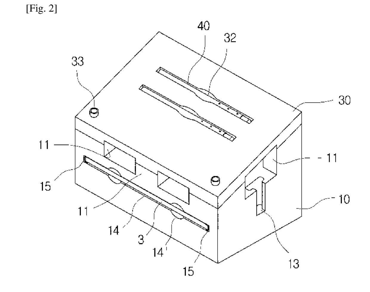
[0024]FIG. 1 is a perspective view illustrating a spread state of an extended photovoltaic module fixture according to the present invention, FIG. 2 is a perspective view illustrating a non-spread state of the extended photovoltaic module fixture according to the present invention, and FIG. 3 is an exploded perspective view illustrating the extended photovoltaic module fixture according to the present invention.

[0025]Referring to FIGS. 1 to 3, the extended photovoltaic module fixture of the present invention includes a main body 10, a hinge part 20, and an auxiliary body 30. By these elem...


PUM


Abstract

An extended photovoltaic module unit comprises: a main body (10) having a first photovoltaic power generation module (1) fixed on a plurality of support parts (11) protruding from the upper surface thereof, and a third photovoltaic power generation module (3) slidably provided as a drawer type in an accommodation space (14) formed from the outer surface of one side thereof to the inside direction; a hinge part (20) formed at one side of an upper part of the main body (10); and an auxiliary body (30) having one side rotatably connected to the main body (10) via the hinge part (20), and having a second photovoltaic power generation module (2) fixed at a module supporting groove (31) of a lower end thereof.

Description

BACKGROUND[0001]The present invention relates to an extended photovoltaic module unit. More particularly, the invention relates to an extended photovoltaic module fixture for installing photovoltaic modules, which allows a plurality of photovoltaic modules to be extended in a folding or sliding manner.[0002]Generally, a method of employing solar energy is typically classified into a solar-heat employing method of performing heating and power generation by using water heated by the sun, and a solar-light employing method of electrically operating various kinds of machines and mechanisms by generating electricity using solar light.[0003]The solar-light employing method is referred to as photovoltaic generation, and a photovoltaic generating unit is classified into a standalone photovoltaic generating unit and a grid-connected photovoltaic generating unit.[0004]The standalone photovoltaic generating unit includes a solar-cell array (solar-cell panel) that is made by coupling a pluralit...

Claims


Application Information

Patent Timeline
Patent Type & Authority Applications(United States)
IPC IPC(8): H02S30/20H02S20/10H02S20/30H02S30/10
CPCH02S30/20H02S20/10H02S30/10H02S20/30F24S25/11F24S2025/012Y02E10/47Y02E10/50
Inventor HONG, HYUNG EUI
Owner WANG CHANG GYUN
Why Eureka
Try Eureka