Operator's seat supporting device for service vehicle

a technology for operating seats and vehicles, which is applied in the direction of vehicle components, vehicle arrangements, chairs, etc., can solve the problems of inability to effectively utilize space, disadvantageous low rigidity in the lateral direction, and difficulty in ensuring strength against load, etc., to achieve convenient cleaning, wide space, and comfortable posture

Inactive Publication Date: 2005-04-07
KOMATSU LTD
View PDF15 Cites 35 Cited by
  • Summary
  • Abstract
  • Description
  • Claims
  • Application Information

AI Technical Summary

Benefits of technology

[0022] With the configuration as described above, an area occupied by a seat supporting section on a floor surface can be reduced, whereby a wide space can be provided under an operator's feet to secure that the operator can take a comfortable posture during the operation.
[0023] Further there is also provided the advantage that a floor surface of the operator's cabin can easily be cleaned.
[0024] With the configuration as described above, in addition to the advantages described above, there is provided the advantage that the height adjustment of the seat can be carried out independently from adjustment of a body weight of an operator sitting thereon with the optimal height provided to secure that the operator can take a more comfortable posture during the operation. Further by making use of a magnetic rheological fluid, a vibration damping force can variably be set according to change of the magnetic field, and a damping force can previously be set according to an operator's body weight, which advantageously improves the buffering effect against a shock by an external force.
[0025] When the configuration as described above is employed, the structure is compact, so that a space required for installation thereof can be reduced, so that the occupied space under operator's feet can be minimized to secure that the operator can take a comfortable posture during the operation.
[0026] With the configuration described above, a damper cylinder functioning as a supporting body has a biaxial slide structure, so that only a further small space is required, and a load is shared by a plurality of damper cylinders, so that the stable supporting force can be obtained without causing any saccadic movement.
[0027] Further with the configuration described above, a rotating mechanism is provided on a supporting plate supported by the damper cylinder, so that a rotating movement can be carried out without spoiling the buffering function of the seat.

Problems solved by technology

Further there is another disadvantage that a damper is provided externally, which disables effective utilization of the space.
In addition, the X-shaped link is generally made from flat steel bars, so that the rigidity in the lateral direction is disadvantageously low, and as the joint section includes a pin, and therefore there is another disadvantage that it is difficult to insure strength against load.
As the mechanism for adjusting a body weight is integrated with that for adjusting the height, it is difficult to achieve the complete balance between an operator's body type and the operator's body weight.
Namely, when an operator is a person not having the standard body type such as a relatively heavy person having the low seating height or a person having the relatively high seating height against the body weight, if a seat height is adjusted to the operator's posture, the buffering function is disadvantageously lost, which is another problem.
In the suspension seat structure as disclosed in the cited reference 1, as dampers having different structures respectively are provided in the front of and at the back of the seat, and the dampers are required to be adjusted discretely, and in addition the damper provided at the back of the seat is attached to an outer side of a backrest of the seat, so that, when an inclination of the backrest is changed, the buffering effect also varies, which is disadvantageous from a view point of structure and not preferable because of its complicated structure.

Method used


Image

  • Operator's seat supporting device for service vehicle
  • Operator's seat supporting device for service vehicle
  • Operator's seat supporting device for service vehicle

Examples


first embodiment

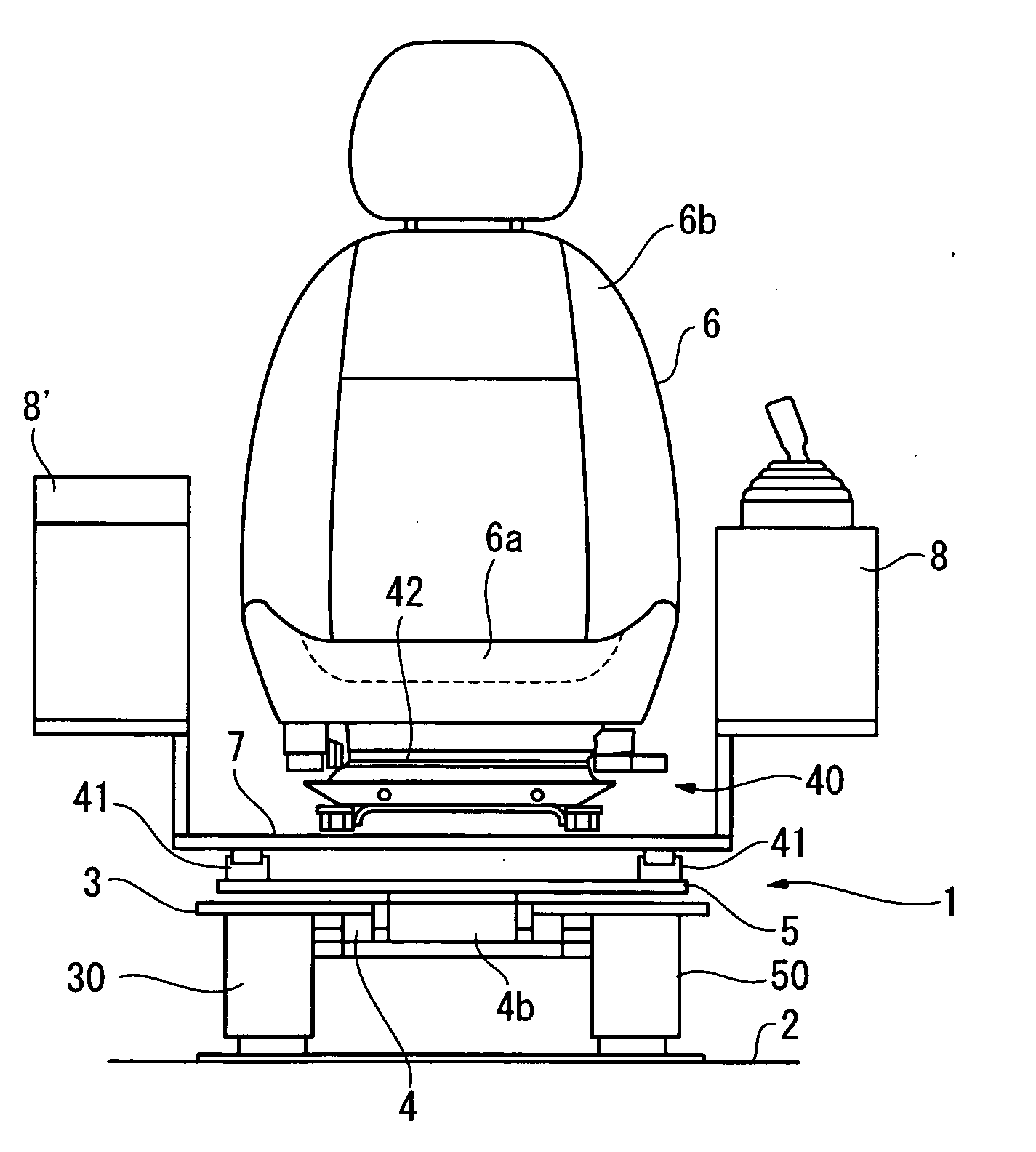
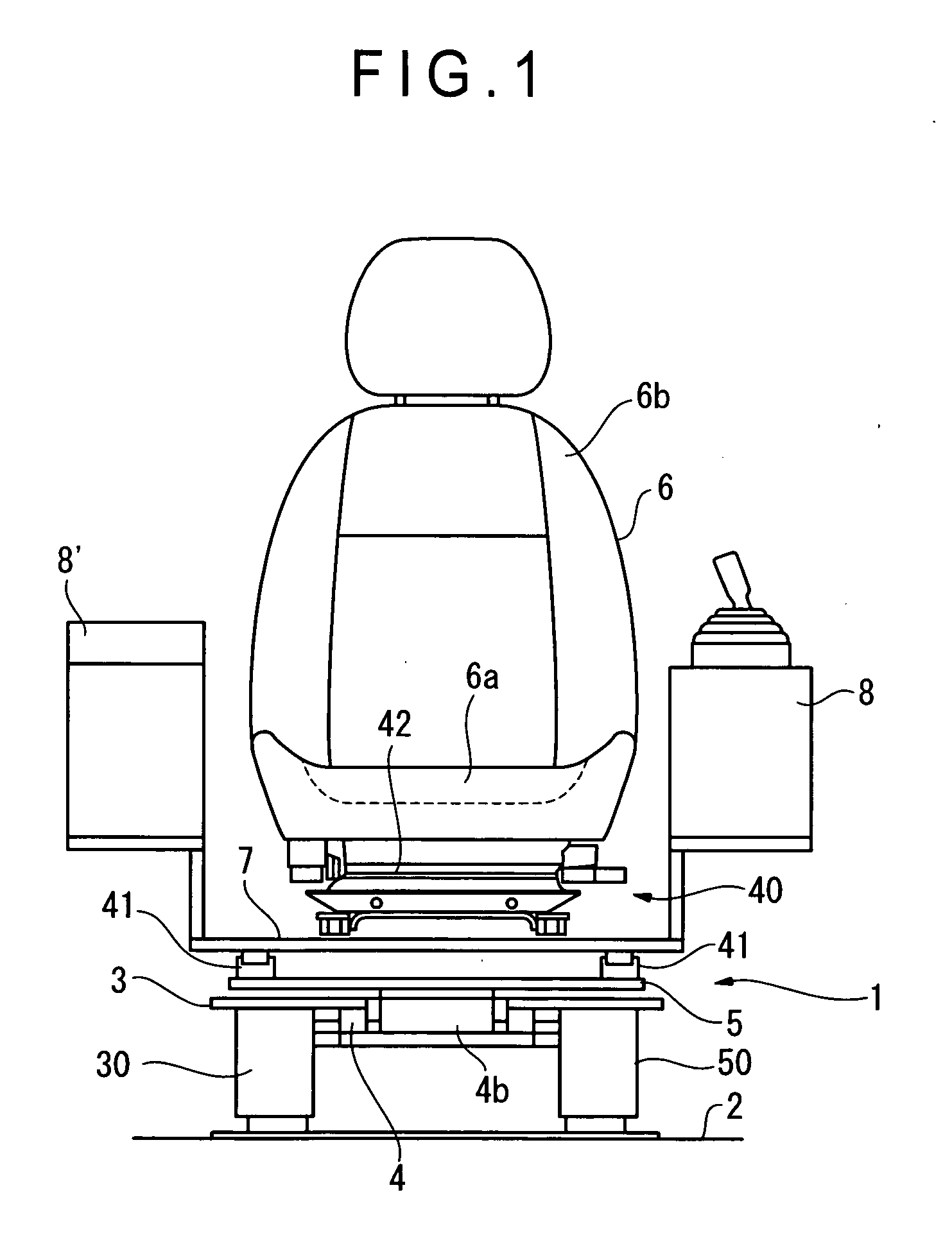
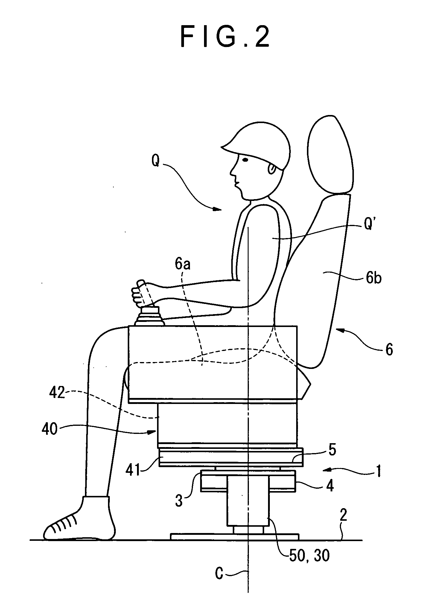
[0039]FIG. 1 is a front elevational view showing a first embodiment of the operator's seat supporting device for a service vehicle according to the present invention; FIG. 2 is a side elevational view of FIG. 1; FIG. 3 is a longitudinal cross-sectional view showing a damping function control mount; FIG. 4 is a cross-sectional view showing the primary portion of the damping function control mount cylinder; and FIG. 5 is a longitudinal cross-sectional view showing a supporting damper.

[0040] An operator's seat supporting device 1 according to this embodiment includes two damper cylinders 50, 30 erecting from and provided on a floor surface 2 of an operator's cabin with a prespecified space; a posture adjusting section 40 provided on a movable supporting plate 5 disposed via a rotating mechanism 4 on a supporting plate 3 supported by these damper cylinders 50, 30; and an operator's seat 6 mounted via this posture adjusting section 40.

[0041] Of the damper cylinders 50, 30, one is a dam...

second embodiment

[0086] Next, referring to FIG. 6, a second embodiment of the present invention is described below.

[0087] In the present embodiment, it is only different from the operator's seat supporting device I according to the first embodiment that the structure of the damper cylinder 50 (damping function control mount cylinder) is modified. In the following, the description of the components have been described already or that of the same components as the above-described components will be omitted or simplified.

[0088] The damper cylinder 10 according to the second embodiment having a magnetic Theological fluid control function includes, as shown in the cross-sectional view in FIG. 6, a buffering cylinder 13 externally and coaxially engaging a fixed member 11 having a mounting base 12 against the floor surface 2 (corresponding to the biaxial slide support structure according to the present invention), a coil spring 19 for restoring a damper provided inside the fixed member 11, and a control ...

third embodiment

[0098] Next, FIG. 8 is a cross-sectional view showing a third embodiment of a damping function control mount cylinder.

[0099] Basic configuration of the damping function control mount cylinder (described simply as a damper cylinder 10A hereinafter) is the same as that in the embodiment described above, but the combinatorial structure is different from that in the embodiment described above. Therefore the basic actions and effects are the same as those described in the respective embodiments described above. It is to be noted that the same reference numerals are assigned to the same components as those in the embodiment described above and detailed description is omitted herefrom. Therefore description is made only to components having different functions respectively.

[0100] The damper cylinder 10A according to this embodiment has a control cylinder 20A incorporated in and at a central position of the buffering cylinder 13A.

[0101] Further a coil spring 19A for restoration is provid...


PUM


Abstract

An operator's seat (6) is mounted via a posture adjusting mechanism (40) on a supporting plate (3) supported by at least two damper cylinders (50, 30) at a place where an operator's seat is installed, and at least one of the damper cylinders (50, 30) is used as a damper cylinder (50) for reducing vibrations by making use of a magnetic rheological fluid.

Description

BACKGROUND OF THE INVENTION [0001] 1. Field of the Invention [0002] The present invention relates to an operator's seat supporting device for a service vehicle having a variable damping mechanism provided mainly in an operator's cabin of a construction machinery and capable of improving the availability. [0003] 2. Description of Related Art [0004] The conventional type of supporting device for an operator's seat provided in an operator's cabin of a construction machine such as a hydraulic shovel or a bulldozer receives a larger shock delivered to the seat on which the operator sits as compared to that delivered to an operator's seat in a general industrial vehicle, and there have been proposed various measures for a suspension structure for reducing the shock. [0005] As a suspension structure for an operator's seat in this type of service vehicle, there has been known one, for instance, as shown in FIG. 9A and FIG. 9B. In this suspension structure, an X-shaped link 102 with the link...

Claims


Application Information

Patent Timeline
Patent Type & Authority Applications(United States)
IPC IPC(8): B60N2/54
CPCB60N2/501B60N2/502B60N2/505B60N2/544B60N2/509B60N2/522B60N2/527B60N2/508
Inventor TSUJI, HIDEKITAMARU, MASATAKE
Owner KOMATSU LTD
Why Eureka
Try Eureka