Swingarm suspension system for vehicle

a technology of suspension system and swingarm, which is applied in the direction of foldable cycles, cycle equipment, cycles, etc., can solve the problems of increasing body weight and load on the link mechanism, and achieve the effect of reducing load or tension

Active Publication Date: 2007-02-20
HONDA MOTOR CO LTD
View PDF13 Cites 31 Cited by
  • Summary
  • Abstract
  • Description
  • Claims
  • Application Information

AI Technical Summary

Benefits of technology

[0009]According to this swingarm suspension system, while a lower end of the shock absorber attached to the swingarm is pressed upwardly for accompanying an upward swinging of the swingarm, the first link moves upwardly together with the swingarm and is pulled out by the second link attached to the vehicle body side, to swing the first link with respect to the swingarm and to press the upper end of the shock absorber downwardly. As a result, the shock absorber is compressed in a direction causing the upper and lower ends to come closer in a stroke direction.
[0010]At this time, a rotational shaft of the first link and the swingarm constitutes a center of oscillation of the first link, and a rotational shaft of the first link and the second link constitutes a power point. Also, a first axis, connecting respective centers of the rotational shaft of the first link and the swingarm and the rotational shaft of the first link and the second link, constitute a swing radius. The power point is pulled towards the vehicle body side by the second link. However, since an angle formed by a second axis, connecting respective centers of the rotational shaft of the second link and the first link and a rotational shaft of the second link and the vehicle body side, and a first axis which is the swing radius is set so as to pass through 90° while the shock absorber reaches from a maximum extension position to a maximum compression position, the second link always pulls the power point at an angle of about 90° with respect to the swing radius. As a result, when the first link is caused to swing, it is possible to minimize a load or tension applied to the second link.

Problems solved by technology

However, in the event that the first link is arranged above the swingarm, since a spatial relationship around the center of the vehicle above the pivot shaft and design freedom for a link mechanism made up of the respective links are limited, this invites an increase in load on the link mechanism, which as a result causes an increase in body weight.

Method used


Image

  • Swingarm suspension system for vehicle
  • Swingarm suspension system for vehicle
  • Swingarm suspension system for vehicle

Examples


Embodiment Construction

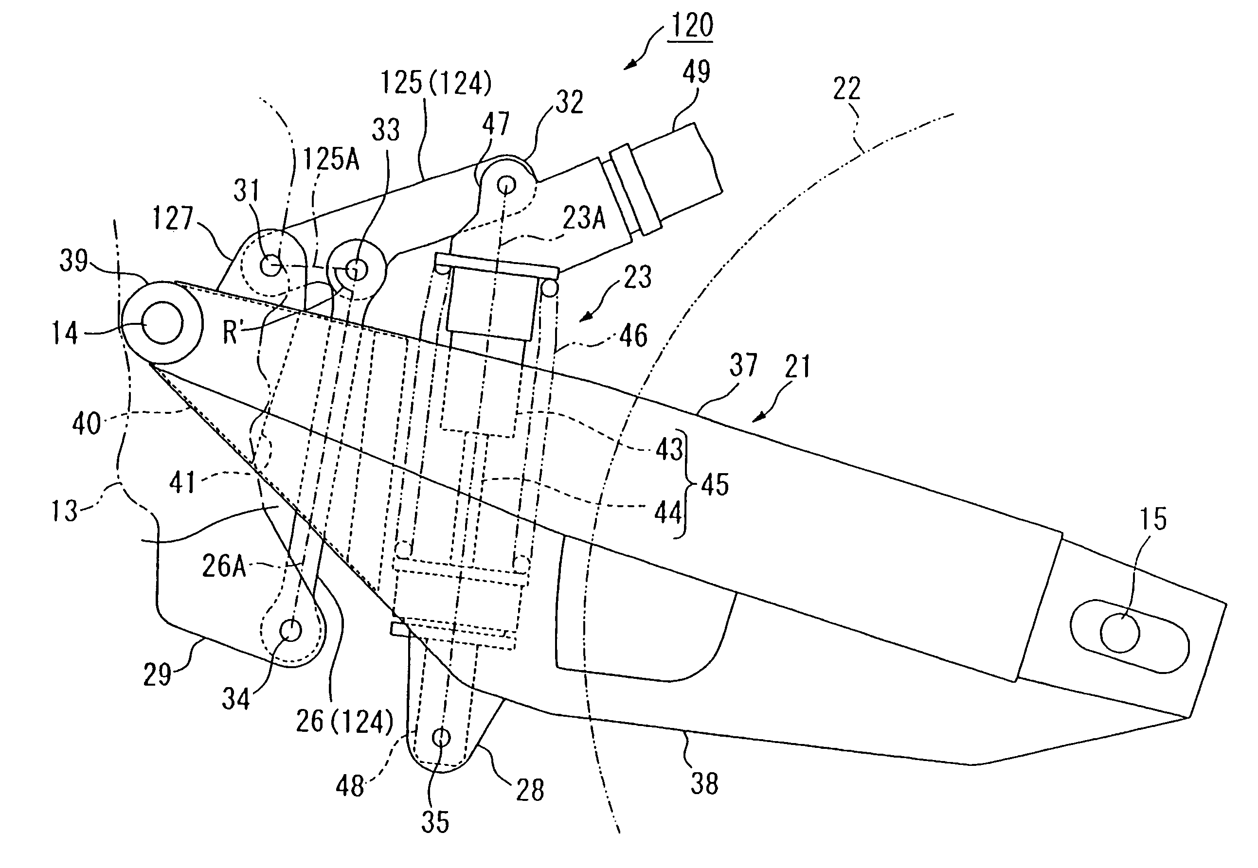
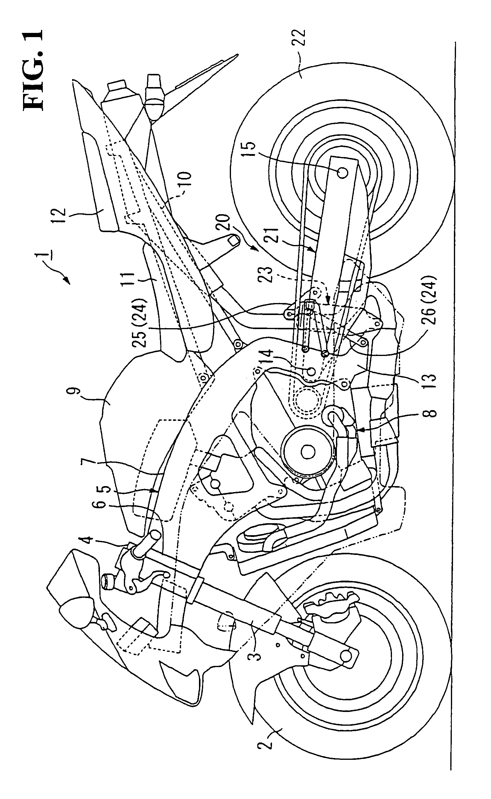
[0023]Embodiments of the invention will now be described with reference to the drawings wherein FIG. 1 is a side elevation of a motorcycle or vehicle provided with the swingarm suspension system of the present invention. As shown in FIG. 1, a front fork 3, axially supporting a front wheel 2 of a motorcycle 1, is attached in a steerable manner to a headpipe 6 of a vehicle frame 5, via a steering stem 4. A power unit 8 that includes an engine and a transmission is attached to a lower part of a main frame 7 of the vehicle frame 5. A fuel tank 9 is attached to an upper part of the main frame 7. A rider's seat 11 and pillion seat 12 for a rearwardly seated rider are respectively attached to an upper part of a seat rail 10 connected to a rear part of the main frame 7. The swingarm suspension system 20 of the present invention is attached to a pivot plate 13 linked to a rear end of the main frame 7.

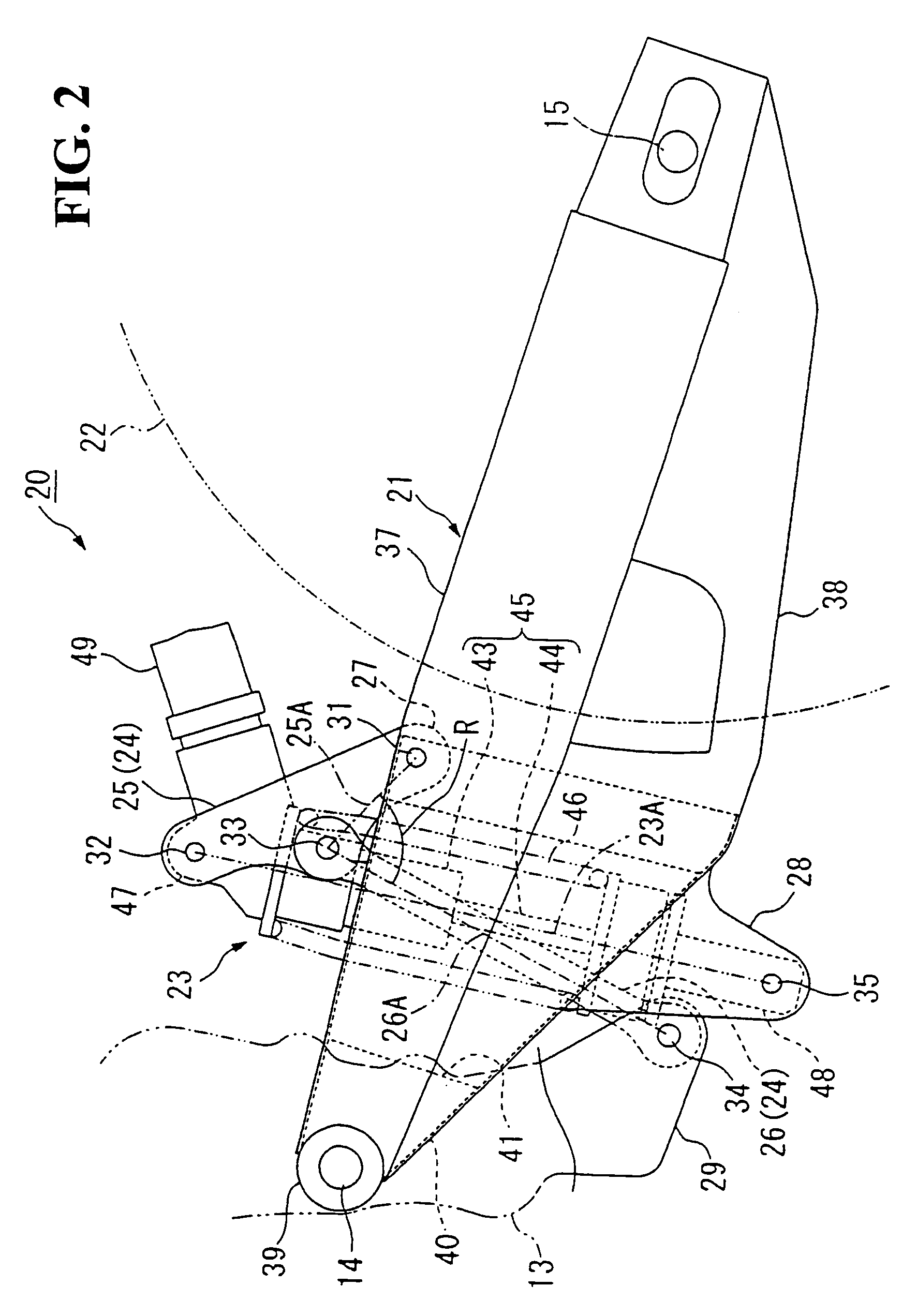
[0024]The swingarm suspension system 20 comprises a swingarm 21 having a front end swingably...


PUM


Abstract

A swingarm suspension system for a vehicle for reducing weight by reducing a load on a link mechanism and reducing a space in the vicinity of the center of the vehicle. A swingarm is attached to a vehicle body side pivot shaft with a shock absorber having a lower end attached to a lower part of the swingarm. A first link is attached to an upper end of the shock absorber and an upper part of the swingarm and a second link is attached to part of the vehicle body side lower down relative to the pivot shaft and the first link. An angle R formed by a first axis, constituting a swing radius of the first link, and a second axis, running along a tension direction of the second link, is set so as to pass through 90° while the shock absorber extends between maximum extension compression positions.

Description

BACKGROUND OF THE INVENTIONCROSS-REFERENCE TO RELATED APPLICATIONS[0001]The present application claims priority under 35 USC 119 to Japanese Patent Application No. 2003-1021125 filed on Apr. 4, 2003 the entire contents thereof is hereby incorporated by reference.[0002]1. Field of the Invention[0003]This invention relates to a swingarm suspension system for a vehicle, provided with a swing arm supporting a vehicle wheel, and a shock absorber attached to this swingarm. More particularly, the present invention relates to an arrangement of a link mechanism attached to the swingarm and the shock absorber.[0004]2. Description of Background Art[0005]Conventionally, a swingarm suspension system for a vehicle includes a swingarm having a vehicle wheel supported on one end that is swingably attached at the other end to a vehicle body side pivot shaft. An upper end of a shock absorber is attached to this swingarm with a lower end of the shock absorber being attached to a first link connected t...

Claims


Application Information

Patent Timeline
Patent Type & Authority Patents(United States)
IPC IPC(8): B62K25/12B62K25/28B62K25/20
CPCB62K25/286B62K25/283
Inventor TOYODA, HIDETOSHI
Owner HONDA MOTOR CO LTD
Why Eureka
Try Eureka