Camera-puddle lamp integrated apparatus and side mirror including the same

a technology of integrated apparatus and side mirror, which is applied in the direction of optical viewing, vehicle components, instruments, etc., can solve the problems of increasing the number of design considerations, the insufficient the inability to install all the necessary function modules, so as to reduce the size of the camera monitor system, reduce manufacturing costs, and ensure the waterproofness of the integrated module

Active Publication Date: 2021-12-16
HYUNDAI MOBIS CO LTD
View PDF0 Cites 0 Cited by
  • Summary
  • Abstract
  • Description
  • Claims
  • Application Information

AI Technical Summary

Benefits of technology

[0009]The present disclosure is directed to providing a side mirror, in which an occupied space in the side mirror is minimized by integrating a camera for a surround view monitor (SVM) with a puddle lamp into one part so that watertightness of an integrated module is easily secured and manufacturing costs are reduced, and providing a camera-puddle lamp integrated module useful for reduction in size of a camera monitor system (CMS).

Problems solved by technology

In particular, in the case of a camera monitor system (CMS) in which a size of a side mirror is dramatically reduced by installing only a camera instead of a mirror to reduce wind noise and improve fuel economy, the CMS has a small size which is insufficient for installing all necessary function modules.
Meanwhile, as the number of modules disposed in the side mirror 1 increases, the number of design considerations for ensuring watertightness of each module increases and costs increase.

Method used


Image

  • Camera-puddle lamp integrated apparatus and side mirror including the same
  • Camera-puddle lamp integrated apparatus and side mirror including the same
  • Camera-puddle lamp integrated apparatus and side mirror including the same

Examples


first embodiment

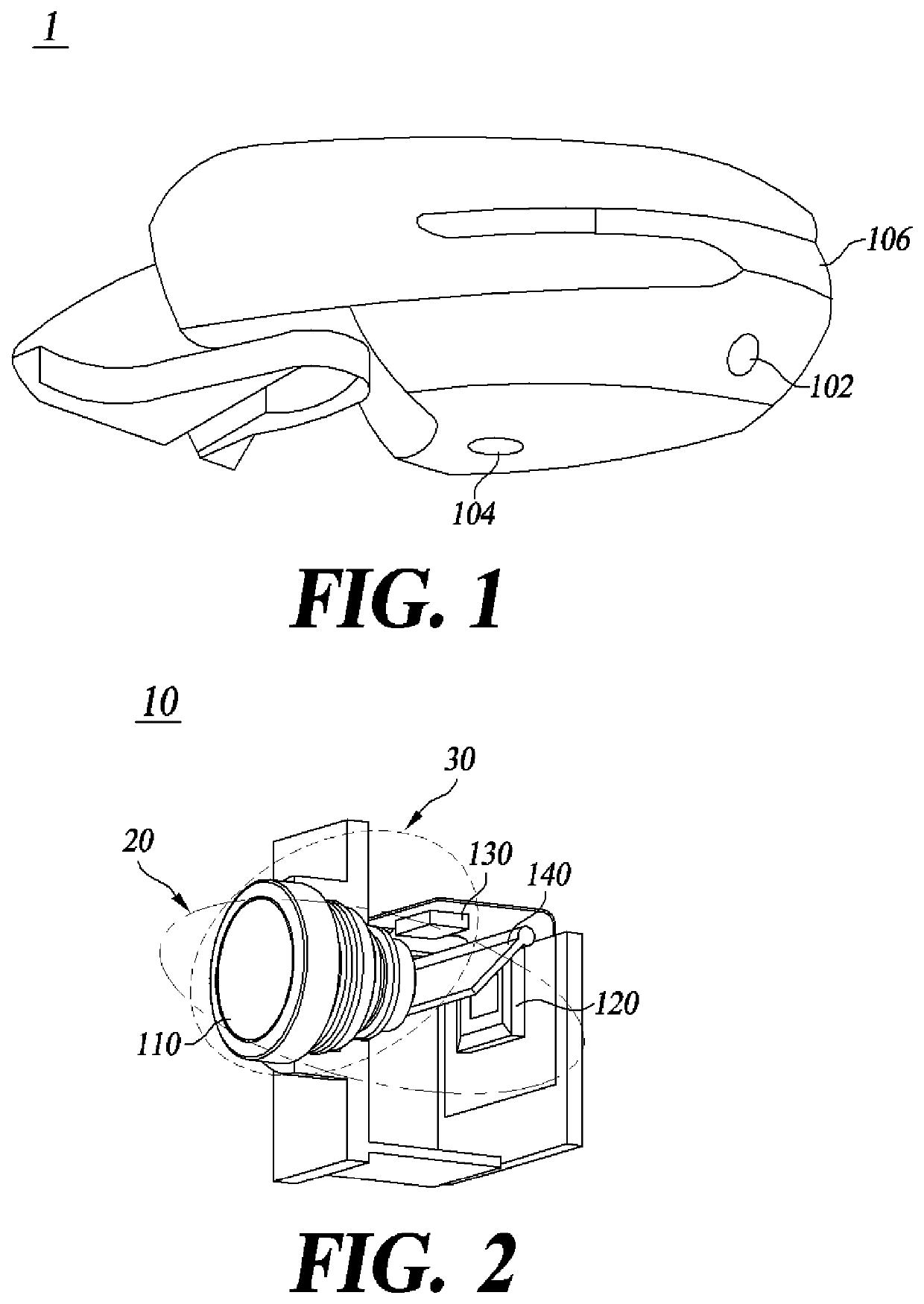
[0024]FIG. 2 is a perspective view illustrating a camera-puddle lamp integrated apparatus according to the present disclosure.

[0025]Referring to FIG. 2, a camera-puddle lamp integrated apparatus 10 according to the first embodiment of the present disclosure includes a lens module 110, an image sensor 120, a light source 130, and a mirror module 140. A camera module 20 and a puddle lamp module 30 share the lens module 110, and the image sensor 120 is spaced apart from the rear of the lens module 110 with a first area therebetween. The mirror module 140 is disposed between the rear of the lens module 110 and the image sensor 120 of the camera module 20. The mirror module 140 includes a mirror 142, and the mirror 142 rotates about one side thereof as a rotation axis so that an operation state of the integrated apparatus 10 is switched.

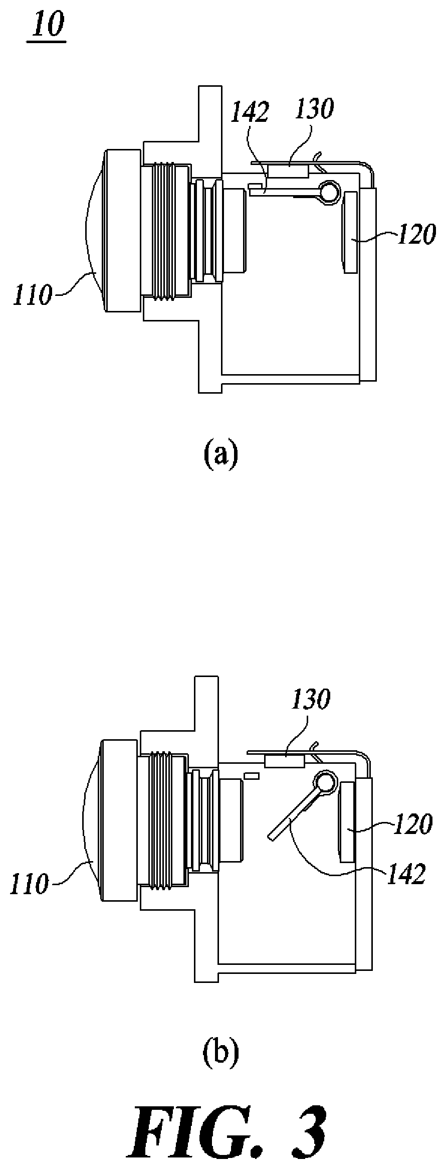
[0026]A state, in which the mirror 142 of the mirror module 140 is lowered to the first area between the rear of the lens module 110 and the image sensor...

second embodiment

[0058]FIG. 7 is a conceptual diagram of a camera-puddle lamp integrated apparatus according to the present disclosure.

[0059]Referring to FIG. 7, in a camera-puddle lamp integrated apparatus 12 according to the second embodiment of the present disclosure, a camera module 22 and a puddle lamp module 32 share the lens module 110, and the puddle lamp module 32 is disposed at a peripheral portion of the image sensor 120. The puddle lamp module 32 according to one embodiment includes a separate optical unit 132 so that light emitted from the light source 130 is directed to a rear end of the lens module 110. In FIG. 7, one end of the optical unit 132 is illustrated to have a wedge shape, but this is only for conceptually illustrating a configuration of one embodiment and is not limited thereto, and various shapes including a circular lens group capable of changing a path of the emitted light may be used.

[0060]In the camera-puddle lamp integrated apparatus 12 according to one embodiment, th...

third embodiment

[0069]FIG. 9 is a side view of a camera-puddle lamp integrated apparatus according to the present disclosure.

[0070]Referring to FIG. 9, in a camera-puddle lamp integrated apparatus 14 according to the third embodiment of the present disclosure, a camera module 24 and a puddle lamp module 34 share the lens module 110, and the image sensor 120 is spaced apart from the rear of the lens module 110 with the first area therebetween. The light source 130 of the puddle lamp module 34 is disposed behind the lens module 110 and is disposed in a second area outside the first area. A light path of the light source 130 and an image light path incident on the image sensor 120 are formed to pass through the lens module 110 using the translucent mirror 143 disposed at the rear of the lens module 110. The translucent mirror 143 may be fixed to a front housing of the camera module 32 on which the lens module 110 is mounted.

[0071]In addition, in order to more efficiently use the light emitted from the...


PUM


Abstract

a camera-puddle lamp integrated apparatus is disclosed. The apparatus comprising a lens module; an image sensor; and a puddle lamp module, the puddle lamp module includes a light source, a spring, a sliding bar, and a solenoid and is disposed in a second area outside the first area, the light source is formed to be movable to be located in the first area or the second area, the light source is fixed to one side of the sliding bar, a moving part of the solenoid is connected to the other side of the sliding bar, and the spring is formed to be operated to move the sliding bar when the solenoid is switched to a non-operational state so as to move the light source to the second area, the camera-puddle lamp integrated apparatus operates as a puddle lamp when the light source moves to the first area, and the camera-puddle lamp integrated apparatus operates as a camera when the light source moves to the second area.

Description

CROSS-REFERENCE TO RELATED APPLICATIONS[0001]This application claims priority to and the benefit of Korean Patent Application No. 10-2020-0070841, filed on Jun. 11, 2020, the disclosure of which is incorporated herein by reference in its entirety.BACKGROUND OF THE INVENTION1. Field of the Invention[0002]The present disclosure relates to a camera-puddle lamp integrated apparatus and a vehicle side mirror including the same.2. Discussion of Related Art[0003]Contents described in this section merely provide background information on the present embodiment and do not constitute the related art.[0004]Among various functions for providing convenience to a driver, there are puddle lamps, surround view monitors (SVMs), or around view cameras.[0005]An SVM is an integrated camera system for providing information on the surrounding environment of a vehicle when parking and is placed in the vehicle to photograph areas in all directions from the vehicle. In general, an SVM camera module 102 for ...

Claims


Application Information

Patent Timeline
Patent Type & Authority Applications(United States)
IPC IPC(8): B60R1/12B60Q1/00
CPCB60R1/1207B60Q1/0023B60Q2400/50B60Q2400/40B60R2001/1253B60Q1/2665G03B15/05G03B30/00G03B2215/0585G03B2215/0567G03B2215/0575G03B2215/0592G03B2215/0503B60Q1/247H04N23/56B60R1/06H04N23/57H04N23/55
Inventor LEE, WON MOOOH, SANG HWANCHOI, EUN HOLEE, HYUN SEOKLEE, TAE YOUN
Owner HYUNDAI MOBIS CO LTD
Why Eureka
Try Eureka