
Air-blade, silencer and separator apparatus and method

a technology of silencer and separator, which is applied in the direction of atomized substances, liquid spraying apparatuses, spray nozzles, etc., to achieve the effect of improving silencing and reducing the probability and power of resonant frequencies

Active Publication Date: 2017-12-14
SEVY EARL VAUGHN
View PDF0 Cites 2 Cited by
  • Summary
  • Abstract
  • Description
  • Claims
  • Application Information

AI Technical Summary

Benefits of technology

The air blade silencer system is designed to improve the separation and silencing of droplets and noise during operation. It uses a channel and drift chamber with large aspect ratios and curved surfaces to reduce resonant frequencies. The system also includes an offset exit port and impingement surfaces to further improve noise reduction. Overall, the system improves the quality of air released from the system.

Problems solved by technology

By direct contact between the material in the jet with the surrounding material, the surrounding material receives momentum from the jet and thereby accelerates, joining and broadening the jet, necessarily slowing it.

Method used


Image

  • Air-blade, silencer and separator apparatus and method
  • Air-blade, silencer and separator apparatus and method
  • Air-blade, silencer and separator apparatus and method

Examples


Embodiment Construction

[0064]It will be readily understood that the components of the present invention, as generally described and illustrated in the drawings herein, could be arranged and designed in a wide variety of different configurations. Thus, the following more detailed description of the embodiments of the system and method of the present invention, as represented in the drawings, is not intended to limit the scope of the invention, as claimed, but is merely representative of various embodiments of the invention. The illustrated embodiments of the invention will be best understood by reference to the drawings, wherein like parts are designated by like numerals throughout.

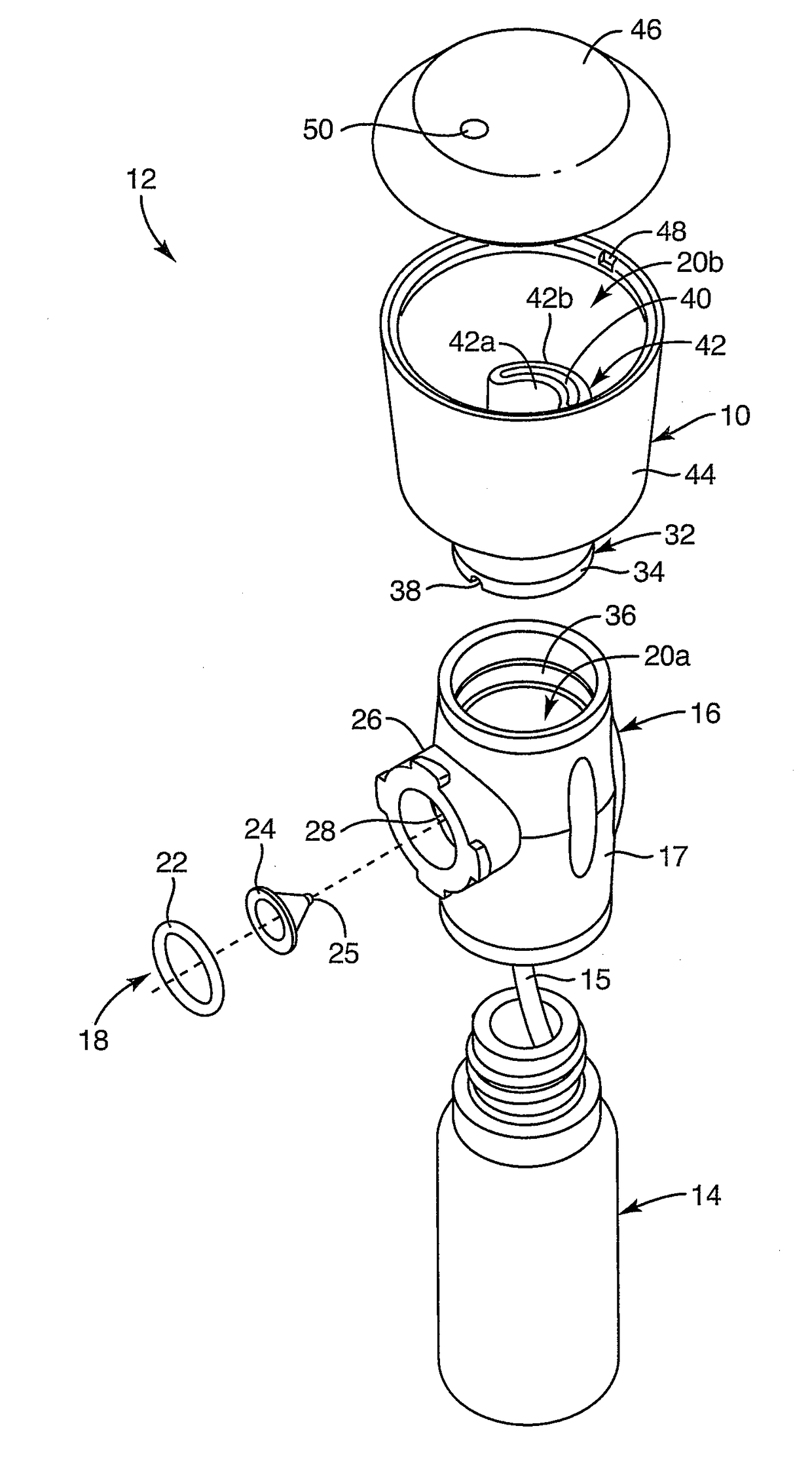
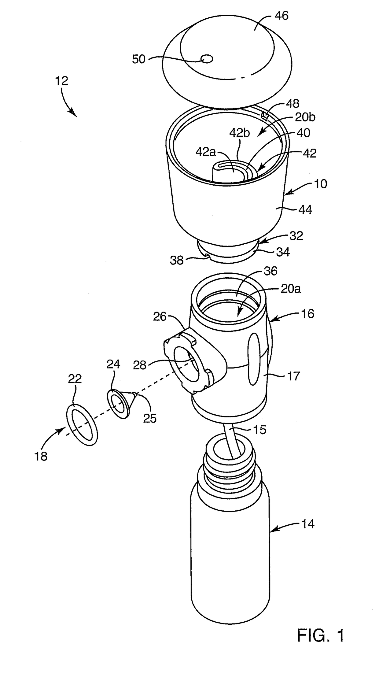
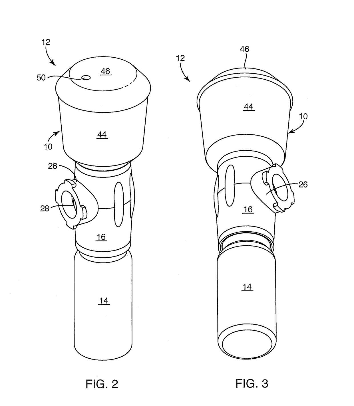
[0065]Referring to FIG. 1, while continuing to refer to FIGS. 1 through 14 generally, a silencer 10 or separator 10 may be configured as an air-blade, silencing, separator apparatus and method. Accordingly, it will be appropriate to speak of the subsystem 10 as a silencer, a separator, an air-blade, or the like. The subsystem 10...


PUM

PropertyMeasurementUnit
aspect ratioaaaaaaaaaa
thicknessaaaaaaaaaa
widthaaaaaaaaaa

Abstract

Silencing and separation in a cold-air, essential-oil, diffuser apparatus and method pass flow through a channel having comparatively high aspect ratios of length to thickness and width to thickness. Curved, tapered, non-parallel, and quasi random surfaces reduce probability and power of resonant frequencies. Offsetting flow through a channel is followed by impingement against an obstructing surface, redirection elsewhere within a drift (separation) chamber, and exiting through a smaller, and differently oriented exit port. Silencing is improved by changes of cross-sectional area creating high-pass and low pass acoustic filters, changes of direction, and absorption of acoustic energy in fluid-droplet-laden air.

Description

RELATED APPLICATIONS[0001]This application claims the benefit of U.S. Provisional Patent Application Ser. No. 62 / 459,013, filed Feb. 14, 2017, and is a continuation-in-part Application of U.S. patent application Ser. No. 29 / 554,486, filed Feb. 11, 2016, both of which are hereby incorporated herein by reference. This application incorporates by reference: U.S. patent application Ser. No. 12 / 247,755, filed Oct. 8, 2008, issued Feb. 1, 2011, as U.S. Pat. No. 7,878,418; U.S. patent application Ser. No. 13 / 854,545, filed Apr. 1, 2013; U.S. patent application Ser. No. 14 / 260,520, filed Apr. 24, 2014; U.S. Provisional Patent Application Ser. No. 62 / 265,820, filed Dec. 10, 2015; U.S. patent application Ser. No. 14 / 850,789, filed Sep. 10, 2015; and U.S. Provisional Patent Application Ser. No. 62 / 277,343, filed Jan. 11, 2016.BACKGROUNDField of the Invention[0002]This invention relates to atomization of liquids and, more particularly, to novel systems and methods for separating larger droplets...

Claims


Application Information

Patent Timeline
Patent Type & Authority Applications(United States)
IPC IPC(8): A61L9/14B05B7/00B05B7/24
CPCA61L9/14B05B7/2489B05B7/0081B05B1/262B05B7/0012B05B7/2424B05B14/00B05B1/002Y02P70/10
Inventor SEVY, EARL VAUGHN
Owner SEVY EARL VAUGHN
Learn More