Air-oil reservoir for an air compressor

a technology of air compressor and air oil, which is applied in the direction of liquid fuel engines, machines/engines, separation processes, etc., can solve the problems of increasing the manufacture cost of the motor compressor and the compressor assembly, unsatisfactory consumption of material and manpower, and increasing the cos

Active Publication Date: 2017-12-14
SCHULZ COMPRESSORES LTDA
View PDF1 Cites 4 Cited by
  • Summary
  • Abstract
  • Description
  • Claims
  • Application Information

AI Technical Summary

Benefits of technology

[0009]Due to the drawbacks mentioned above and related to the known constructive solutions, it is the object of the present invention to provide an air-oil reservoir, formed in a single piece of cast iron (or aluminum and steel) and which allows an air compressor, for example a rotary screw air compressor to be directly affixed and operatively coupled thereon, without requiring the provision of tubular connections and / or peripheral fittings, external to the air-oil reservoir, for coupling said devices for the treatment of the compressed air-oil flow to be released to the points of consumption.

Problems solved by technology

Although allowing different models of compressor to be affixed on the same base plate of the reservoir, this type of mounting arrangement requires, for each compressor model, the provision of a specific support frame, usually constructed in metallic plate portions, which need to be shaped or welded, with undesirable consumption of material and manpower.
Although it simplifies and compacts the structural elements of the mounting arrangement of both the air-oil reservoir and the compressor, eliminating the structural frame for the motor-compressor assembly and the tubular connection, in a separate piece, between the outlet of the compressor and the air-oil reservoir, this prior art construction still presents the drawback of having the air-oil reservoir superiorly shaped as a function of each compressor model to be affixed thereon, requiring the manufacture of different models of reservoir made of cast iron, each model designed to receive a specific compressor model.
Such characteristic increases the manufacture cost of the motor-compressor-reservoir assembly.
This type of construction requires the provision of a plurality of tubular connections and / or peripheral fittings which increase the cost and weaken the mounting arrangement.

Method used


Image

  • Air-oil reservoir for an air compressor
  • Air-oil reservoir for an air compressor
  • Air-oil reservoir for an air compressor

Examples


Embodiment Construction

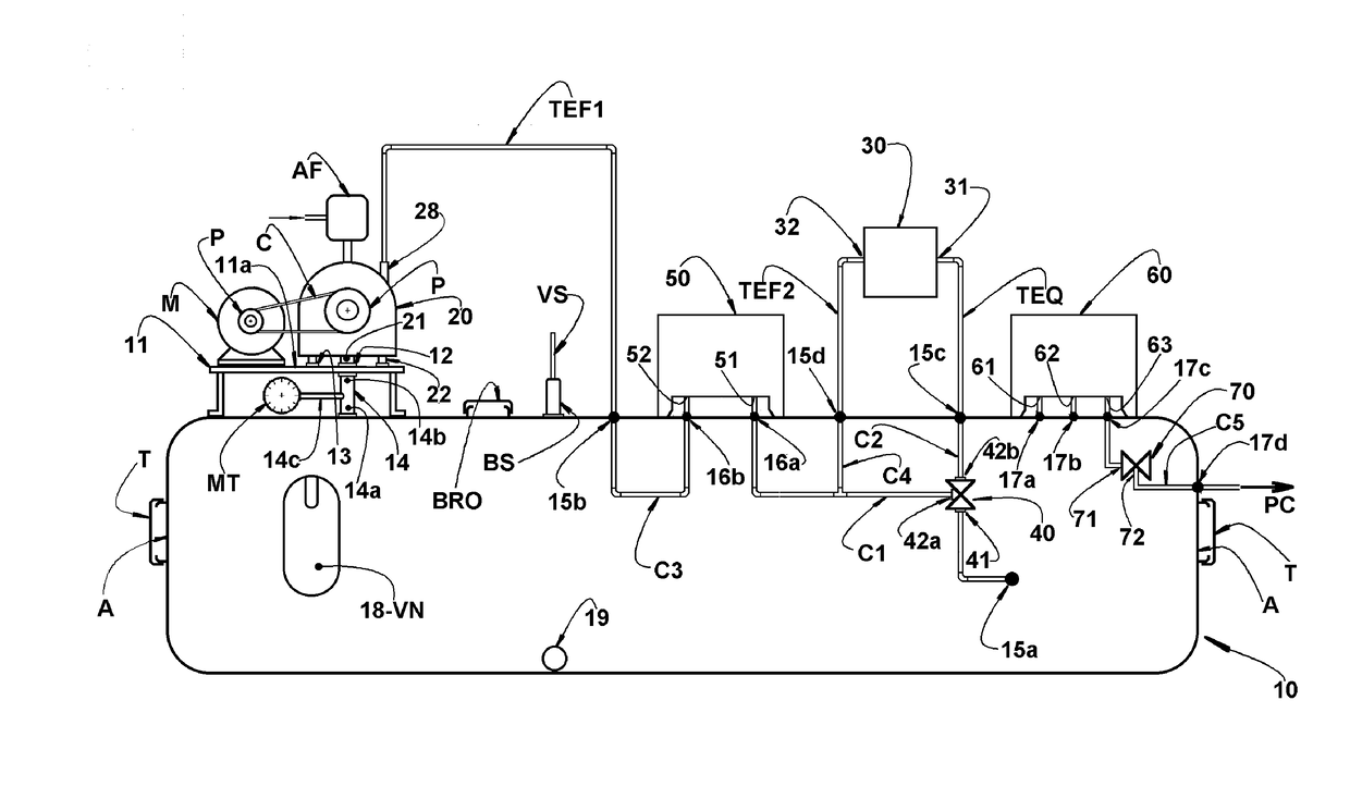
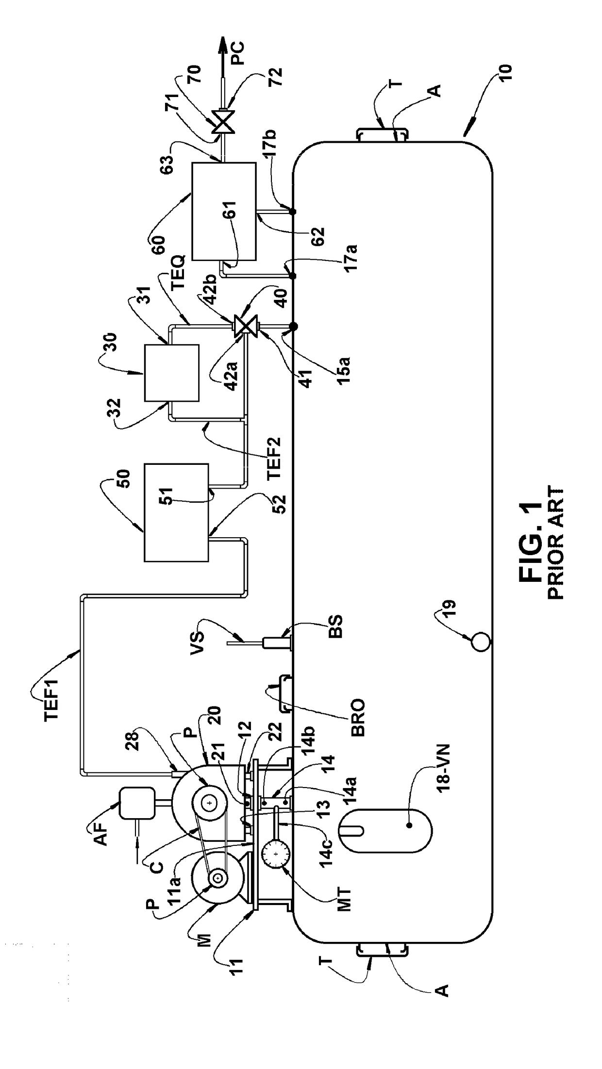
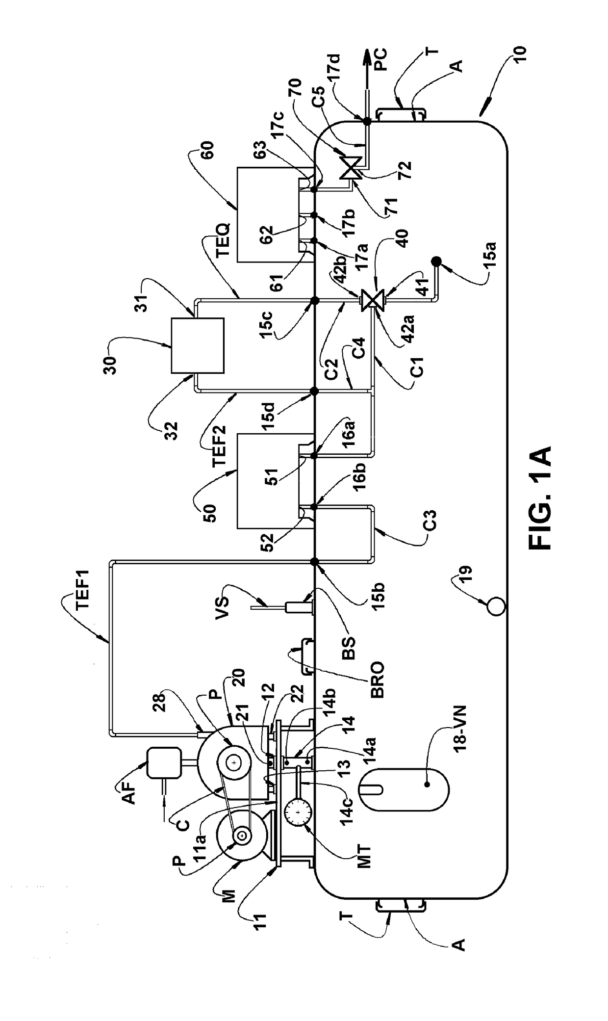
[0024]As already discussed and illustrated in the appended drawings, the present air-oil reservoir 10 is of the type constructed in a single piece, usually in cast iron and to be used in a mounting arrangement with an air compressor 20, usually of the rotary screw type, which is inferiorly provided with an air-oil flow discharge nozzle 21 and with support and anchoring shoes 22, the latter being usually provided with threaded holes (not illustrated), designed for receiving respective fixation screws 25 (see FIG. 8).

[0025]The air-oil compressor 20 is usually driven by a motor M, usually electric, by means of an adequate transmission, which may be defined by an assembly of pulleys P and belts C. The air compressor 20 may present different models with a power of about, for example, 15 HP, but which may vary from about 5 HP to 20 HP, and different drilling patterns in its shoes 22, said air compressor 20 being further provided with the usual devices for admission and filtration AF of th...


PUM

PropertyMeasurementUnit
pressureaaaaaaaaaa
temperatureaaaaaaaaaa
poweraaaaaaaaaa

Abstract

The compressor is inferiorly provided with a discharge nozzle and with shoes which are seated and affixed against a support plate, incorporated to the air-oil reservoir and provided with an admission hole aligned with the discharge nozzle, and with a tubular column, incorporated to the air-oil reservoir and open to the interior of the latter. The air-oil reservoir further presents: an inner housing receiving a thermostatic valve, connected to the interior of the air-oil reservoir and also to the compressor and to an oil radiator, as a separate device, through cold oil outlet and hot oil outlet nozzles of the air-oil reservoir; openings for the direct coupling of an oil filter and of an air-oil separating filter; and an end housing lodging a minimum pressure valve.

Description

FIELD OF THE INVENTION[0001]The present invention refers to an air-oil reservoir of the type constructed in a single piece of cast iron (or aluminum or steel) and to be used in a mounting arrangement with an air compressor, usually of the rotary screw type and, for example, with a power from 5 to 20 HP, in order to define a compact assembly for producing compressed air, using a reduced number of external tubular connections.PRIOR ART[0002]There are well known in the prior art the rotary screw air compressors, of the type usually affixed, jointly with the respective motor, in the same support frame, the compressor being operatively connected, by means of external tubes, to an air-oil reservoir.[0003]In said known technical solutions, the support frame and the air-oil reservoir are usually affixed onto a base plate, with the reservoir being somewhat spaced from the compressor, requiring the provision of different tube extensions with the respective connections, in order to operational...

Claims


Application Information

Patent Timeline
Patent Type & Authority Applications(United States)
IPC IPC(8): F04C29/02
CPCF04C29/026B01D2267/40B01D45/02B01D45/06B01D46/0031B01D45/08B01D46/62
Inventor KRAUS, GILBERTOJUNIOR, NELSON SANTI
Owner SCHULZ COMPRESSORES LTDA
Why Eureka
Try Eureka