
Bubble lamp structure for qusai air bubble flow

a technology of bubble lamp and bubble lamp, which is applied in the direction of lighting, decorative arts, lighting and heating apparatus, etc., can solve the problems of easy breakage of one of the bubble lamp parts, unsatisfactory conventional bubble lamp parts, etc., and achieve excellent heat conduction effect and prevent easy damage to glass tubes or bulbs

Inactive Publication Date: 2017-12-14
LIN CHIN SAN
View PDF4 Cites 0 Cited by
  • Summary
  • Abstract
  • Description
  • Claims
  • Application Information

AI Technical Summary

Benefits of technology

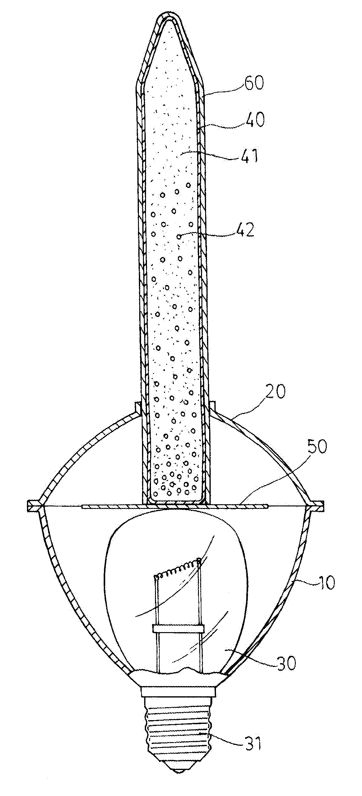
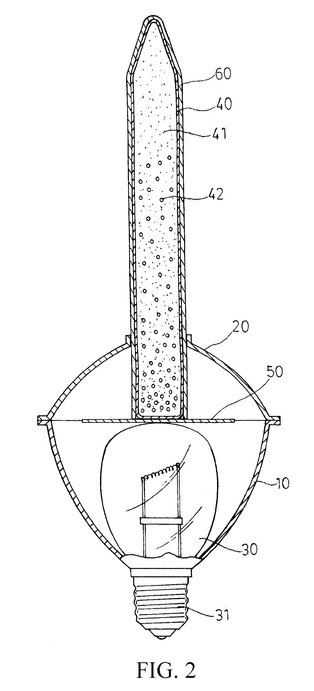
The present invention is about a new bubble lamp structure that prevents damage to the glass tube or bulb during assembly or use. A buffer made of transparent material is placed on top of the bulb or at the bottom of the glass tube to absorb impact and prevent damage. A casing made of transparent and durable material surrounds the glass tube to further protect it from damage. This helps prevent the bulb or glass tube from being broken easily, and also allows for effective heat conduction and protection from external force.

Problems solved by technology

But, the bubble lamp structure mentioned above has the defects: the glass-made glass tube and bulb must be abutted against each other after assembly, and the best heat conduction effect can then be achieved.
However, if the contact force between the glass tube and bulb is too large upon assembly, one of them is easy to be broken.
Furthermore, the glass tube and bulb are expanded due to temperature change upon the direct contact and abutment thereof to cause them to push each other, probably resulting in the rupture thereof.
Therefore, conventional bubble lamp structures are not ideal, necessary to be improved.

Method used


Image

  • Bubble lamp structure for qusai air bubble flow
  • Bubble lamp structure for qusai air bubble flow
  • Bubble lamp structure for qusai air bubble flow

Examples


Embodiment Construction

[0009]Referring to FIG. 2, a bubble lamp for quasi bubble flow of the present invention mainly includes a main body 10, upper cover 20, bulb 30, glass tube 40, buffer 50 and casing 60. An opening is configured on the top of the main body 10, and a smaller circular hole on the bottom thereof; the bulb 30 is placed on the main body 10, and a screw base 31 on the bottom of the bulb 30 is passed through the circular hole to expose out of the main body 10; an opening is configured on the bottom of the upper cover 20, and a smaller circular hole on the top thereof; fluid 41 with a low boiling point and several fine color particles 42 are filled in the glass tube 40; the glass tube 40 is inserted in the upper cover 20 through the circular hole, and the upper half of the glass tube 40 is exposed out of the top of the upper cover 20 the present invention is characterized in that the buffer 50 made of a transparent material having an excellent heat conduction effect and impact moderating perf...


PUM


Abstract

Disclosed is a bubble lamp for quasi bubble flow. A buffer made of a transparent material having an excellent heat conduction effect and impact moderating performance is configured on the top of the bulb configured on the main body of the bubble lamp or on the bottom of the glass tube configured on the upper cover, and the casing made of a transparent and no-easily-broken material is put around the glass tube, thereby abutting the glass tube against the top of the bulb across the buffer when the upper cover is covered on and coupled to the main body, allowing both the glass-made bulb and glass tube to be buffered by the butter and thus to block or decrease an impact when a contact force is too large upon assembly, and preventing the bulb or glass tube from being broken.

Description

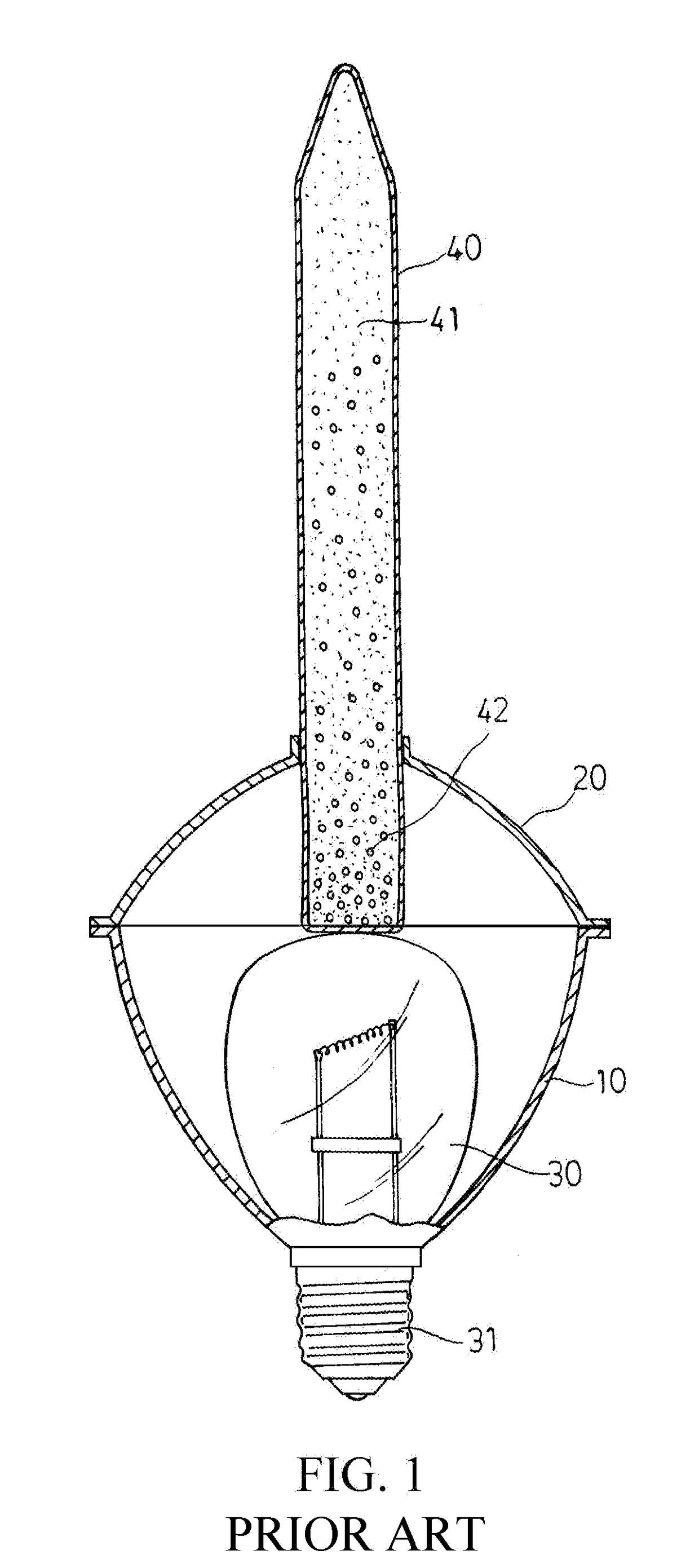
(a) TECHNICAL FIELD OF THE INVENTION[0001]The present invention relates to a lamp structure, and more particularly to a bubble lamp structure, inside which quasi air bubble flow is generated by means of high temperature.(b) DESCRIPTION OF THE PRIOR ART[0002]A bubble lamp for quasi bubble flow is a lamp having a bulb on which a glass tube inside which quasi bubble flow is generated by means of high temperature is configured. The bubble lamp for quasi bubble flow, as FIG. 1 shows, mainly includes a main body 10, upper cover 20, bulb 30 and glass tube 40 inside which fluid 41 with a low boiling point and several fine color particles 42. An opening is configured on the top of the main body 10, and a smaller circular hole the bottom thereof; the bulb 30 is placed on the main body 10, and a screw base 31 on the bottom of the bulb 30 is passed through the circular hole to expose out of the main body 10; an opening is configured on the bottom of the upper cover 20, and a smaller circular ho...

Claims


Application Information

Patent Timeline
IPC IPC(8): F21S10/00F21V15/00
CPCF21V15/00F21S10/002F21W2121/00
Inventor LIN, CHIN-SAN
Owner LIN CHIN SAN
Learn More