Elastic wave device

a technology of elastic wave and device, applied in the direction of piezoelectric/electrostrictive/magnetostrictive devices, electrical apparatus, impedence networks, etc., can solve the problem of difficulty in providing elastic wave devices capable of supporting various frequency bands, and achieve the effect of more effective change of acoustic velocity of s0 mode, and more effective change of s0 mod

Active Publication Date: 2017-12-14
MURATA MFG CO LTD
View PDF4 Cites 10 Cited by
  • Summary
  • Abstract
  • Description
  • Claims
  • Application Information

AI Technical Summary

Benefits of technology

[0010]In another aspect of an elastic wave device according to a preferred embodiment of the present invention, the plurality of grooves are provided in the lower surface of the piezoelectric thin film, the respective grooves are positioned under the electrode fingers of the IDT electrode, and the projection is positioned under a region between the electrode fingers. In this case, adjusting the height of the projection makes it possible to easily change an acoustic velocity of an SH0 mode, S0 mode, or the like.
[0021]Various preferred embodiments of the present invention utilizes an S0 or SH0 mode so that elastic wave devices with various acoustic velocities are able to be provided with ease.

Problems solved by technology

As such, it is difficult to provide an elastic wave device capable of supporting various frequency bands with a plate wave such as an S0 mode, SH0 mode, or the like.

Method used


Image

  • Elastic wave device
  • Elastic wave device
  • Elastic wave device

Examples


first preferred embodiment

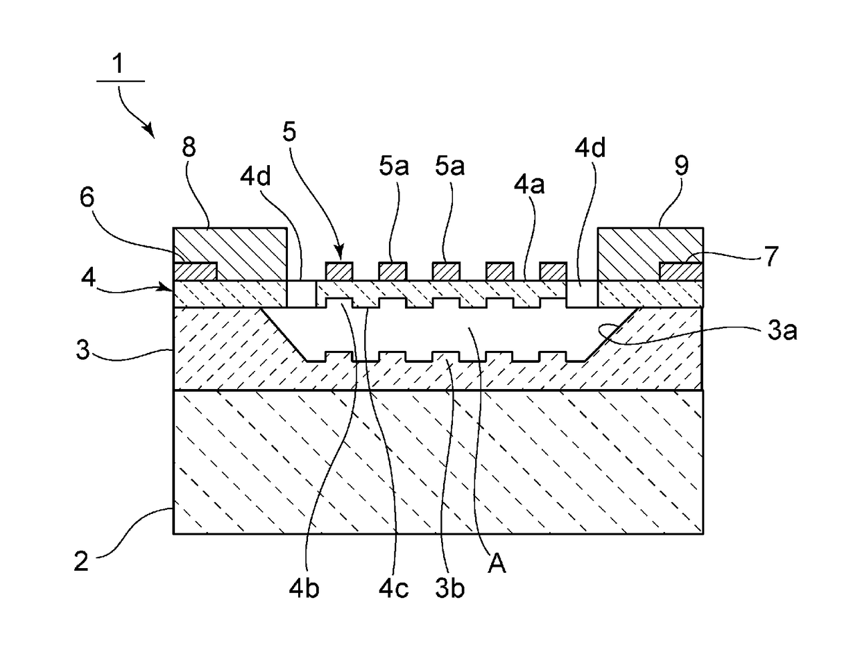
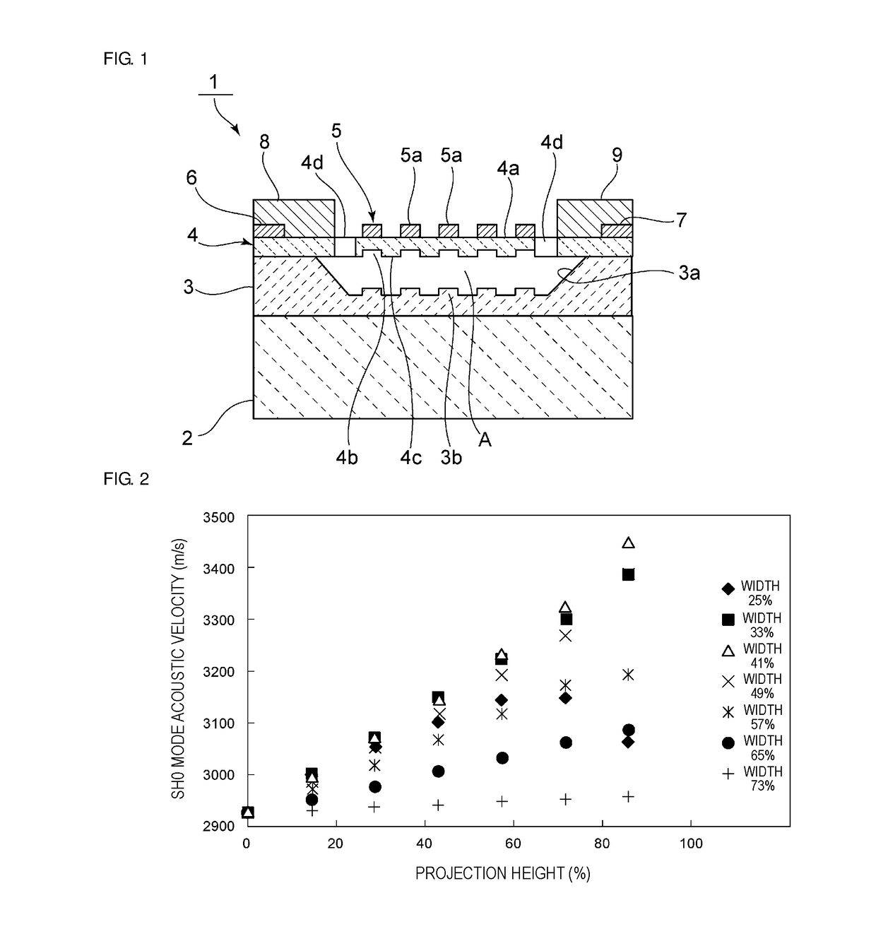
[0041]FIG. 1 is a cross-sectional front view of an elastic wave device according to a first preferred embodiment of the present invention.

[0042]An elastic wave device 1 includes a support including a support substrate 2 and a support layer 3. The support layer is provided on the support substrate 2. A recess 3a is provided in an upper surface of the support layer 3. A piezoelectric thin film 4 is laminated on the support layer 3 so as to cover the recess 3a, thus making the inside of the recess 3a be a hollow section A. A portion of the piezoelectric thin film 4 that is positioned on the hollow section A becomes an exciting section.

[0043]In the exciting section, an IDT electrode 5 is provided on an upper surface 4a of the piezoelectric thin film 4. The IDT electrode 5 includes a plurality of electrode fingers 5a.

[0044]On the piezoelectric thin film 4, a wiring 6 and a wiring 7 are each provided in a region of an outer side portion of the hollow section A. The wiring 6 and the wirin...

second preferred embodiment

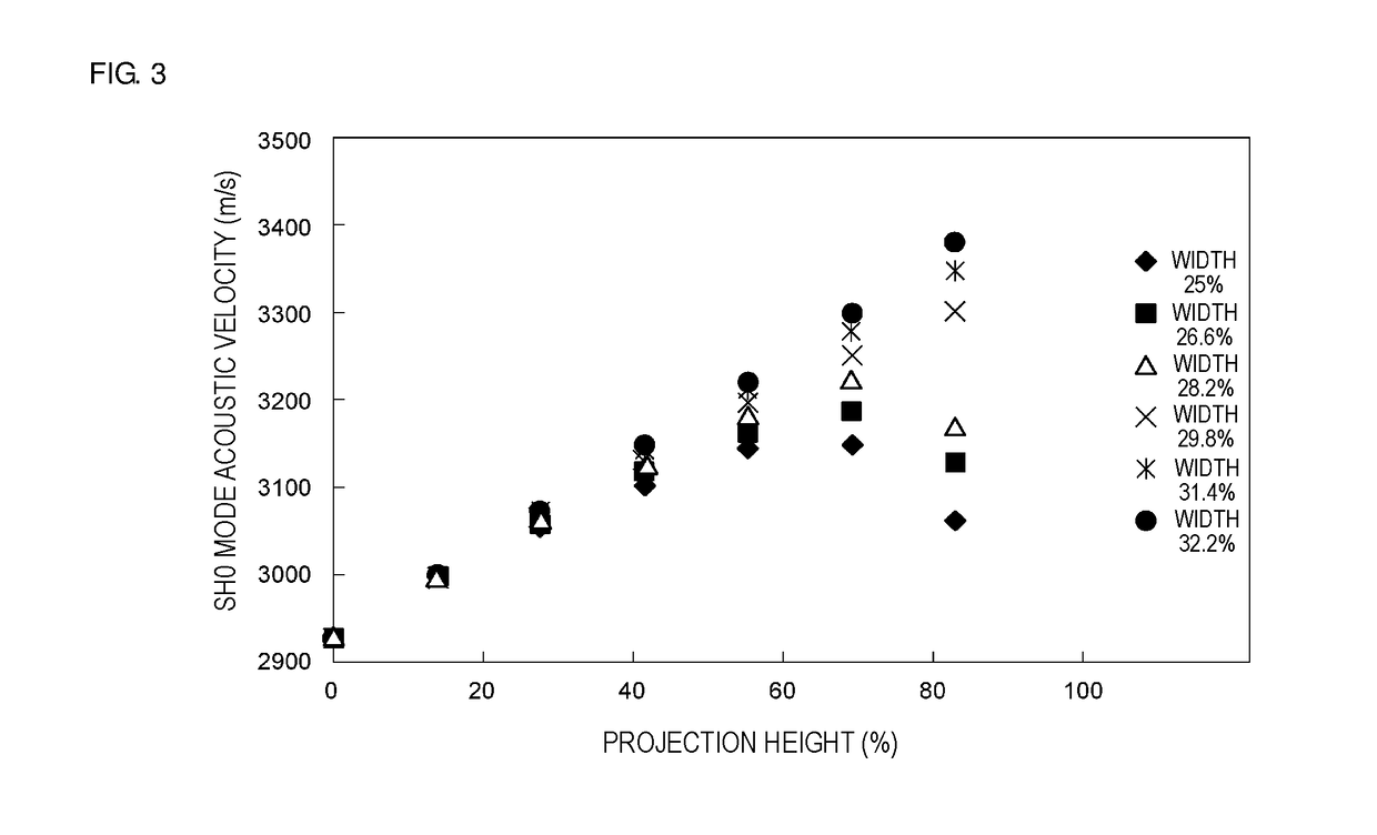
[0078]An elastic wave device according to a second preferred embodiment of the present invention preferably has the same or similar structure as the elastic wave device 1 of the first preferred embodiment except that an S0 mode as a plane wave is used. Note that, however, in order to excite the S0 mode effectively, a LiNbO3 substrate with Euler angles being about (90°, 90°, 40°) is used as the piezoelectric thin film 4. Further, the thickness of the piezoelectric thin film 4 made of LiNbO3 is preferably about 0.1λ, and an Al film with a thickness of about 0.07λ is preferably used as the IDT electrode 5, for example. FIG. 7 illustrates a relationship between the acoustic velocity of the S0 mode and the height (%) and width (%) of the projection 4c in this case.

[0079]Like in FIG. 2, the height (%) of the projection in FIG. 7 refers to a ratio of the height of the projection 4c to the thickness of the piezoelectric thin film 4. In other words, it is a ratio (%) of the height of the pro...

third preferred embodiment

[0086]FIG. 8 is a cross-sectional front view of an elastic wave device according to a third preferred embodiment of the present invention.

[0087]An elastic wave device 21 is provided with a plurality of grooves 4e in an upper surface 4a of a piezoelectric thin film 4. A portion between the grooves 4e adjacent to each other defines a projection 4f. Electrode fingers 5a of an IDT electrode 5 are each positioned on the projection 4f. On the other hand, grooves or projections are not provided in a lower surface of the piezoelectric thin film 4. A bottom surface of a support layer 3 facing a hollow section A is flattened. Other elements of the elastic wave device 21 are preferably the same or similar to those of the elastic wave device 1.

[0088]The plurality of grooves 4e are each provided at a region between the electrode fingers 5a of the IDT electrode 5. Meanwhile, the projection 4f is provided immediately under the electrode finger 5a. In the present preferred embodiment, the grooves 4...


PUM


Abstract

An elastic wave device in which a recess is provided on an upper side of a support, a piezoelectric thin film covers the recess, and an IDT electrode is provided on an upper surface of the piezoelectric thin film. A plate wave of an S0 mode or SH0 mode is used. A plurality of grooves are provided in the upper surface or lower surface of the piezoelectric thin film at a portion of the piezoelectric thin film that is positioned on a hollow section.

Description

CROSS REFERENCE TO RELATED APPLICATIONS[0001]This application claims the benefit of priority to Japanese Patent Application No. 2016-117181 filed on Jun. 13, 2016. The entire contents of this application are hereby incorporated herein by reference.BACKGROUND OF THE INVENTION1. Field of the Invention[0002]The present invention relates to elastic wave devices that utilize plate waves propagating in piezoelectric thin films.2. Description of the Related Art[0003]Elastic wave devices utilizing plate waves are known. For example, Japanese Unexamined Patent Application Publication No. 2010-154505 discloses an elastic wave device utilizing a lamb wave of a plate wave. In the elastic wave device described in Japanese Unexamined Patent Application Publication No. 2010-154505, a frame-shaped support film is laminated on a support substrate. On the support film, a piezoelectric thin film is laminated. An interdigital transducer (IDT) electrode is provided on an upper surface of the piezoelectr...

Claims


Application Information

Patent Timeline
Patent Type & Authority Applications(United States)
IPC IPC(8): H01L41/107H01L41/047H03H9/17H03H9/56
CPCH01L41/107H03H9/564H03H9/172H01L41/0471H03H9/02228H03H9/174H03H9/02055H03H9/02614H03H9/02574H10N30/40H10N30/871
Inventor KISHIMOTO, YUTAKAKIMURA, TETSUYA
Owner MURATA MFG CO LTD
Why Eureka
Try Eureka