All-secondary air cooled industrial steam condenser

Inactive Publication Date: 2017-12-21
EVAPCO
View PDF8 Cites 21 Cited by
  • Summary
  • Abstract
  • Description
  • Claims
  • Application Information

AI Technical Summary

Benefits of technology

[0027]Additionally, the ACC design of the present invention can be si

Problems solved by technology

The first stage configuration is thermally efficient; however, it does not provide a means for removing non-condensable gases.
Another part of the l

Method used


Image

  • All-secondary air cooled industrial steam condenser
  • All-secondary air cooled industrial steam condenser
  • All-secondary air cooled industrial steam condenser

Examples


Example

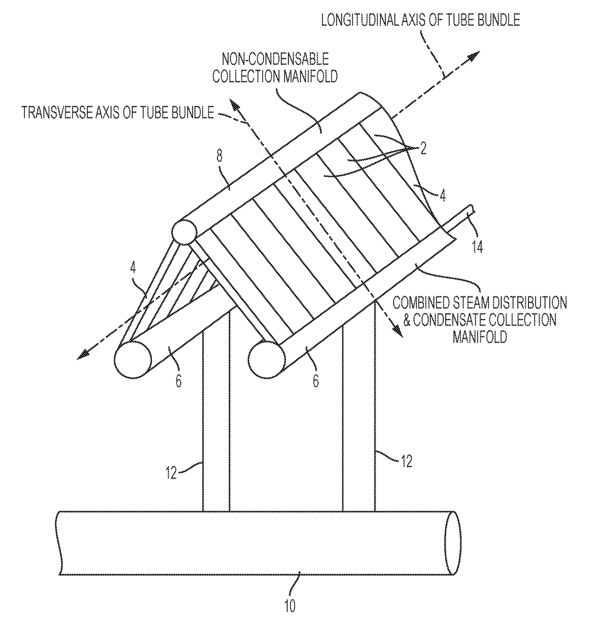
[0042]A-Frame ACC with All Secondary Bundles

[0043]Referring to FIG. 2, tubes 2 are arranged in secondary bundles 4. The longitudinal axes of the tubes 2 are aligned parallel with the transverse axis of the tube bundle, each tube generally oriented 25°-35°, and preferably 30°, from the vertical). Combination steam distribution / condensation collection manifolds 6 are attached at the bottom of each of two secondary bundles 4 that are joined at their top in an A-frame configuration. Steam is distributed to the tubes 2 via the combined steam distribution / condensate collection manifolds 6, and condensate forms in the tubes 2 as the steam condenses and travels down the tubes 2 into the combined steam distribution / condensate collection manifold 6. A single non-condensable collection manifold 8 is attached to the top of both bundles 6 to collect the non-condensable gases that travel to the top of the tubes 2. Steam is supplied to the combined steam distribution / condensate collection manifold...


PUM


Abstract

A new design for large scale field erected industrial steam condensers in which all of the bundles are constructed as secondary bundles, in A-frame or V-Shape configuration, with tubes oriented 25-35 degrees from the vertical, steam fed from the bottom and condensate is collected from the bundles from the bottom using a combination/hybrid manifold that both delivers steam to the tubes and collects condensate from the tubes and which is constructed so that the condensate is prevented from returning down the steam delivery riser(s) and in which the cross-sectional dimensions of the tubes are 125 mm wide with a cross-section height of less than 10 mm with fins that are 9.25 mm in height, arranged at 9 to 12 fins per inch.

Description

BACKGROUND OF THE INVENTIONField of the Invention[0001]The present invention relates to large scale field erected air cooled industrial steam condensers.Description of the Background[0002]The current finned tube used in most large scale field erected air cooled industrial steam condensers (“ACC”) uses a flattened tube that is approximately 11 meters long by 200 mm wide (also referred to as “air travel length”) with semi-circular leading and trailing edges, and 18.8 mm internal height (perpendicular to the air travel length). Tube wall thickness is 1.35 mm. Fins are brazed to both flat sides of each tube. The fins are usually 18.5 mm tall, spaced at 11 fins per inch. The fin surface has a wavy pattern to enhance heat transfer and help fin stiffness. The standard spacing between tubes, center to center, is 57.2 mm. The tubes themselves make up approximately one third of the cross sectional face area (perpendicular to the air flow direction); whereas the fins make up nearly two thirds ...

Claims


Application Information

Patent Timeline
IPC IPC(8): F28B1/06
CPCF28B2001/065F28B1/06F25B39/04F28D1/0426F25B2339/04F28F9/02F28F2009/0287
Inventor BUGLER, III, THOMAS W.LIBERT, JEAN-PIERREHUBER, MARK
Owner EVAPCO
Why Eureka
Try Eureka