Saw magnetic sensor and manufacturing method for same

a technology of magnetic sensor and manufacturing method, which is applied in the field of magnetic sensor, can solve the problems of complicated preparation process and too many uncontrollable factors

Active Publication Date: 2017-12-21
AAC TECH PTE LTD
View PDF14 Cites 5 Cited by
  • Summary
  • Abstract
  • Description
  • Claims
  • Application Information

AI Technical Summary

Problems solved by technology

The SAW Magnetic Sensor has a sensor sensitive unit with too many film layer structure

Method used


Image

  • Saw magnetic sensor and manufacturing method for same
  • Saw magnetic sensor and manufacturing method for same
  • Saw magnetic sensor and manufacturing method for same

Examples


Embodiment Construction

[0010]The present invention will hereinafter be described in detail with reference to an exemplary embodiment. To make the technical problems to be solved, technical solutions and beneficial effects of present disclosure more apparent, the present disclosure is described in further detail together with the figures and the embodiment. It should be understood the specific embodiments described hereby is only to explain this disclosure, not intended to limit this disclosure.

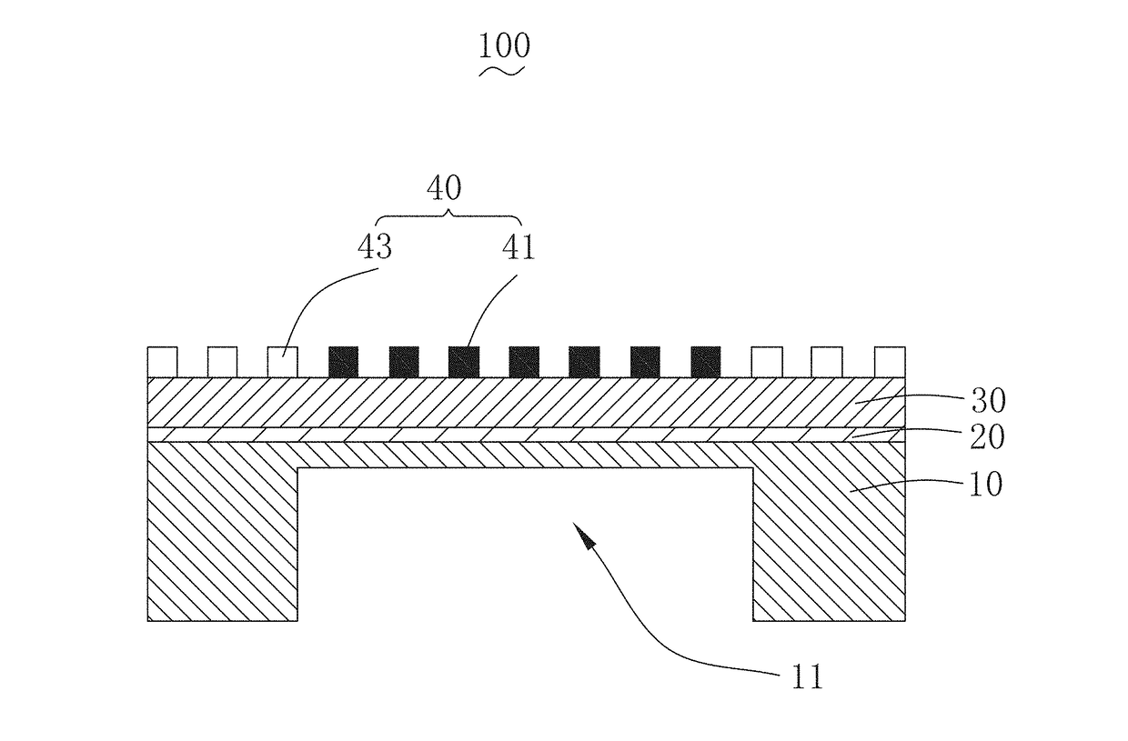
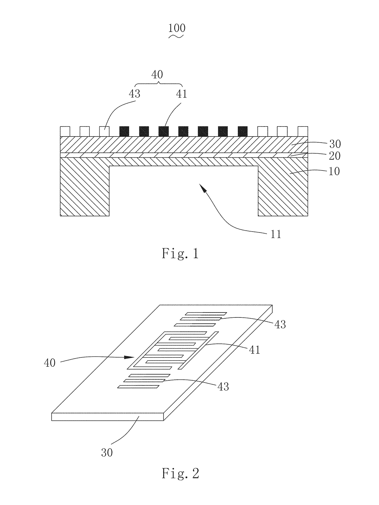
[0011]Referring FIGS. 1-2, the SAW magnetic sensor 100 comprises a underlying substrate 10, a seed layer 20, a piezoelectric thin film 30 and a interdigital transducer 40 stacked from bottom to top. The underlying substrate 10 is provided on the lower surface of the seed layer 20 (i.e., the surface of the seed layer 20 far away from the piezoelectric thin film 30), the piezoelectric thin film 30 is provided on the upper surface of the seed layer 20 (i.e., the surface of seed layer 20 far away from the underlying sub...


PUM


Abstract

A SAW (Surface Acoustic Wave) magnetic sensor includes: a piezoelectric thin film; a seed layer; an interdigital transducer arranged respectively on each side of the piezoelectric thin film, the interdigital transducer comprising an interdigital electrode made from magnetic materials, and reflector grids located at both ends of the interdigital electrode; an underlying substrate arranged at the seed layer opposite to the piezoelectric thin film. A manufacturing method for the sensor is also disclosed.

Description

FIELD OF THE INVENTION[0001]The invention relates to the technical field of magnetic sensors, and more specifically, to a SAW Magnetic Sensor and a manufacturing method thereof.DESCRIPTION OF RELATED ART[0002]Currently, with the rapid development of information industry, industrial automation, electric and electronic technology, transportation, medical instruments, office automation, household electrical appliances and so on as well as popular use of electronic computer, there exists a huge demand for sensors to transform the tested non-electric parameter into electric signal compatible with computer, thus providing opportunities for the rapid development of magnetic sensor and forming a rather considerable magnetic sensor industry. Traditional magnetic sensor comprises sensors such as those based on Holzer effect, anisotropic magneto resistance effect, giant magneto resistance effect, magneto impedance effect, magnetic induction effect, magneto elastic effect, Faraday effect of ele...

Claims


Application Information

Patent Timeline
IPC IPC(8): G01N29/24
CPCG01N29/2462G01N29/2437G01N29/2412G01R33/0052G01R33/02G01N29/2468G01N2291/02863G01R33/095
Inventor TONG, BEILI, YANGZHOU, ZHUOFANOUYANG, JUNZHU, BENPENG
Owner AAC TECH PTE LTD
Why Eureka
Try Eureka