
Work heating device and work treatment device

a heating device and treatment device technology, applied in ohmic resistance heating, ohmic resistance heating details, electrical devices, etc., can solve the problems of affecting the quality of the resultant thin film or the like, and the heat transmission to the work piece takes a long time, so as to achieve the effect of high reliability, quick heat response to the work piece, and simplified layer structur

Active Publication Date: 2013-10-24
CREATIVE TECH CORP
View PDF11 Cites 9 Cited by
  • Summary
  • Abstract
  • Description
  • Claims
  • Application Information

AI Technical Summary

Benefits of technology

The present invention is a work heating device that prevents warping and deformation by using an electric attraction force between the chuck member and the heater member. This eliminates internal stress caused by thermal expansion differences between the two members during heating. The device also has a simplified layer structure, resulting in quicker heat response to a work piece. The heat from the heater member is efficiently transmitted to the work piece, and the temperature can be controlled finely by providing a through hole in the heater member. The device can also be easily attached and detached from each other, making maintenance and replacement parts convenient.

Problems solved by technology

In these types of treatment, the temperature of the work piece determines the film forming rate, the etching rate, and the like, thereby affecting the quality of the resultant thin film or the like significantly.
However, in unitary work attraction devices where components, including ceramic green sheets on which conductive ink is used for printing, are sintered at once, it is difficult to achieve uniformity in heating temperature throughout the entire surface of a work piece due to an error in the thickness of the heating element, an error in the distance from the heating element to the work piece, and the like.
Heat transmission to the work piece consequently takes that much longer time, and more different types of materials result in complicated work temperature control and difficulty in carrying out fine temperature control which affects the quality of a thin film or the like.
On the other hand, the chuck member of a conventional layered-structured work heating device can be warped or bent, or even cracked in some cases, when the work heating device is in use for a long duration, which means that the lifespan of the chuck member determines the product lifespan of the work heating device itself.

Method used


Image

  • Work heating device and work treatment device
  • Work heating device and work treatment device
  • Work heating device and work treatment device

Examples


first embodiment

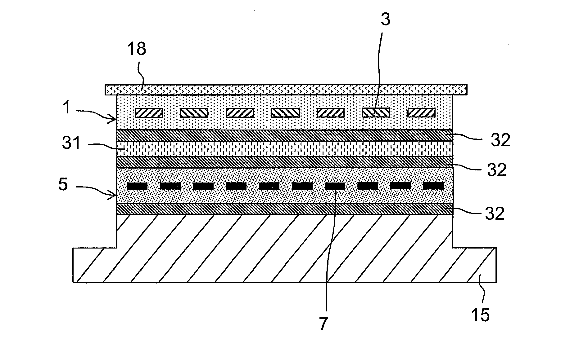
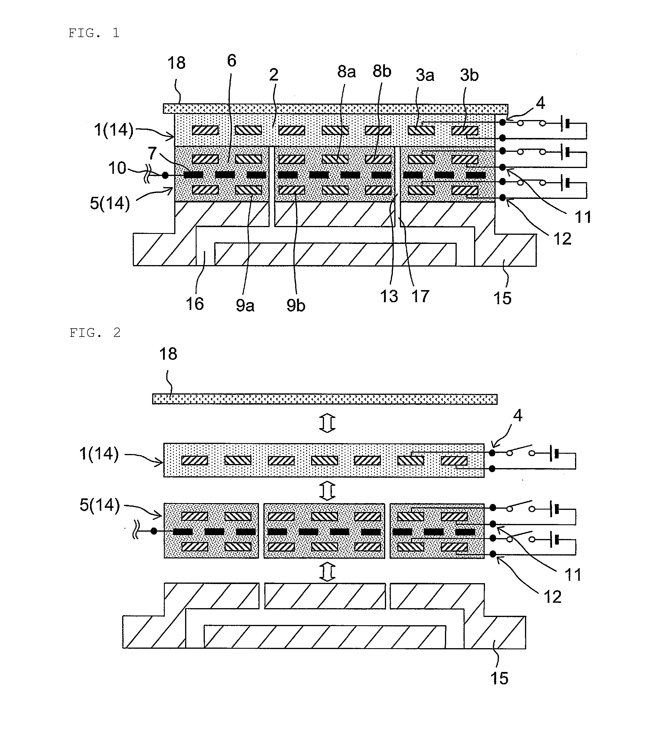
[0037]FIGS. 1 and 2 illustrate a work treating device that can be applied to a plasma etching device which uses plasma for the plasma etching of a semiconductor substrate, or a similar device. In this work treating device, a work heating device 14 which includes a chuck member 1 and a heater member 5 is put on a base platform 15 which has, on the inside, a conduit 16 for flowing gas and which is made from an aluminum alloy. A work piece 18 such as a semiconductor substrate is stuck by attraction to the chuck member side of the work heating device 14 in order to conduct given treatment, for example, plasma etching, while keeping the work piece 18 at a temperature suitable for plasma treatment.

[0038]Among those components, the chuck member 1 is structured so that a work attraction electrode 3 for work attraction is included inside a dielectric substance 2. The chuck member 1 is suited to the shape of a work piece to be treated, and is formed with the use of, for example, two disc-shap...

second embodiment

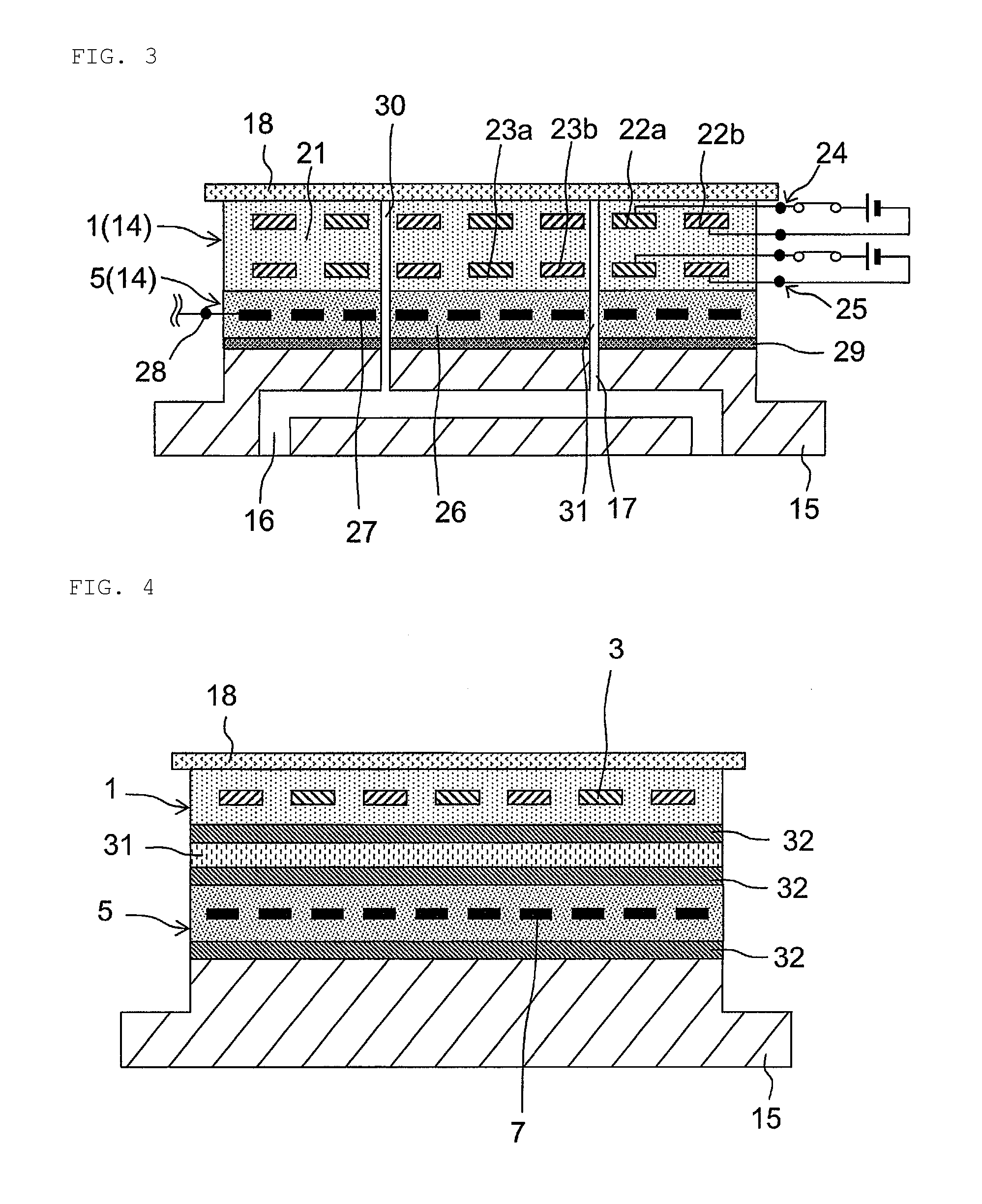
[0044]FIG. 3 illustrates a work treating device that uses a modification example of the work heating device of the present invention. In the work treating device according to a second embodiment of the present invention, the work heating device 14 which includes the chuck member 1 and the heater member 5 is put on the base platform 15 which is made from an aluminum alloy via a attraction sheet 29 which is bonded on the heater member side.

[0045]Among those components, the chuck member 1 is structured so that a work attraction electrode 22 for work attraction and a heater attraction electrode 23 for causing the heater member 5 to stick by attraction are provided inside a dielectric substance 21. Among those components, the heater attraction electrode 23 is placed between a surface of the chuck member 1 that is opposed to the heater member and the work attraction electrode 22. This chuck member 1 is formed by, for example, preparing a ceramic plate made of alumina having one surface on...


PUM


Abstract

Provided are a work heating device which is capable of heating a work piece with high soaking properties as well as fine temperature control and which remains highly reliable over a long-term use by preventing the deformation or the like of a chuck member, and a work treating device that uses the work heating device. The work heating device is a work heating device in which the chuck member including a work attraction electrode for work attraction and a heater member including a heating element for work heating are layered, and which is capable of heating with the heater member the work piece stuck by attraction on the chuck member side, in which the heater member includes a chuck attraction electrode for causing the chuck member to stick by attraction, between a surface of the heater member that is opposed to the chuck member and the heating element, so that the chuck member and the heater member are layered detachably. The work treating device is obtained by putting the work heating device on a base platform.

Description

TECHNICAL FIELD[0001]The present invention relates to a work heating device and a work treating device and, more particularly, to a work heating device capable of heating a work piece such as a semiconductor wafer or a glass substrate while causing the work piece to stick by electric attraction force and a work treating device that uses the same.BACKGROUND ART[0002]The manufacture of a semiconductor device, a liquid crystal device, or the like requires forming a thin film on a work piece such as a semiconductor wafer or a glass substrate, and performing sputtering, etching, and other similar types of treatment on the work piece. In these types of treatment, the temperature of the work piece determines the film forming rate, the etching rate, and the like, thereby affecting the quality of the resultant thin film or the like significantly. For that reason, the forming of a thin film or other similar types of treatment is performed with the use of a unitary work heating device as in, f...

Claims


Application Information

Patent Timeline
Patent Type & Authority Applications(United States)
IPC IPC(8): H01L21/67H01L21/683
CPCH01L21/67103H01L21/6833H01L21/68785H01L21/683
Inventor TATSUMI, YOSHIAKIKAWAE, MEGUMUTEMMA, YASUYUKISUGAWARA, TOSHIFUMI
Owner CREATIVE TECH CORP
Learn More