
Image processing apparatus, image processing method, and program

a technology of image processing and apparatus, applied in the field of image processing apparatus, image processing method, and program, can solve the problems of user inability to perform intuitive operations, the direction of the arrow for changing the numerical value may not match the and the user's intuition may not match the actual moving direction of the cross-sectional plan

Active Publication Date: 2017-12-21
KK TOSHIBA
View PDF5 Cites 6 Cited by
  • Summary
  • Abstract
  • Description
  • Claims
  • Application Information

AI Technical Summary

Benefits of technology

The present invention relates to an image processing apparatus, method, and program that can display a three-dimensional space on a computer screen. The apparatus includes a two-dimensional area information storage unit, a three-dimensional space information storage unit, an operation acquisition unit, a reference guide rail decision unit, a moving direction determination unit, a motion vector calculation unit, a guide rail information generation unit, and a display device. The technical effect of this invention is to provide a more intuitive and smooth user experience when moving a cross-sectional plane in a three-dimensional space, as the user interface allows for a more accurate and matching movement direction.

Problems solved by technology

However, since there are different viewpoints between an area in which the cross-sectional plane to be moved is displayed and the projection plane of the three-dimensional space, a moving direction intuited by the user may not match an actual moving direction of the cross-sectional plane.
In this case, the user cannot perform an intuitive operation and this may cause frustration.
However, a moving direction of the arrow for changing the numerical value may not match the moving direction of the cross-sectional plane in some cases.
In this case, there is a possibility that a smooth operation cannot performed by the user.

Method used


Image

  • Image processing apparatus, image processing method, and program
  • Image processing apparatus, image processing method, and program
  • Image processing apparatus, image processing method, and program

Examples


first embodiment

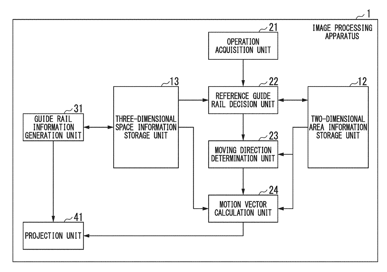
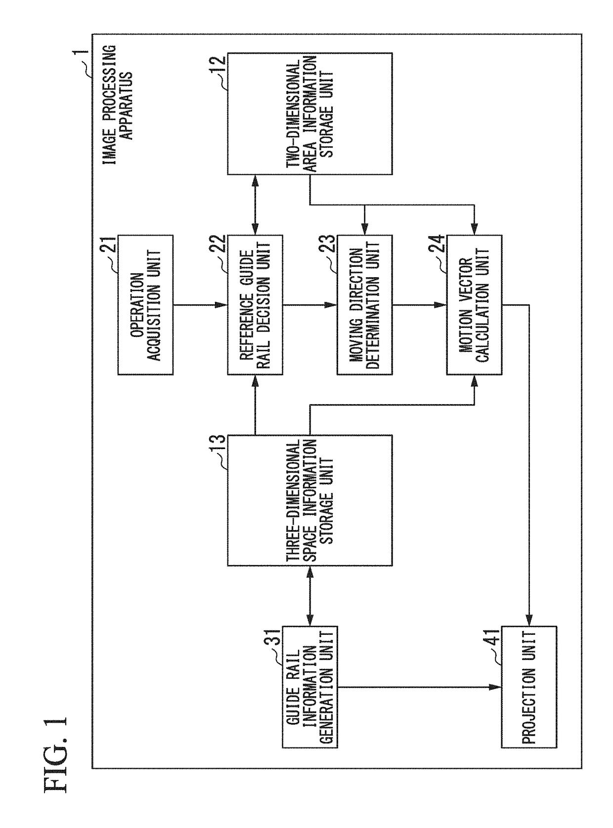
[0017]FIG. 1 is a block diagram which shows a schematic functional configuration of an image processing apparatus of a first embodiment. As illustrated, an image processing apparatus 1 is configured to include a two-dimensional area information storage unit 12, a three-dimensional space information storage unit 13, an operation acquisition unit 21, a reference guide rail decision unit 22, a moving direction determination unit 23, a motion vector calculation unit 24, a guide rail information generation unit 31, and a projection unit 41.

[0018]The image processing apparatus 1 models various objects and the like in a virtual three-dimensional space, and displays an image obtained as a result of projecting these objects onto a projection plane on a screen and the like. The image processing apparatus 1 is realized as an information processing apparatus using an electronic circuit. The two-dimensional area information storage unit 12 and the three-dimensional space information storage unit...

second embodiment

[0119]Next, a second embodiment will be described. A description for the items described in the previous embodiment may be omitted herein. Here, specific items of the present embodiment will be described.

[0120]A block diagram which shows a functional configuration of the present embodiment is as shown in FIG. 1.

[0121]A characteristic of the present embodiment is that the image processing apparatus 1 does not display a guide rail. In other words, the projection unit 41 of the present embodiment projects and draws objects other than a guide rail onto the projection plane, but does not draw the guide rail. Even when the guide rail is not displayed, an operation of the image processing apparatus 1 after a slide operation by a user is detected is the same as that described in the first embodiment. That is, the reference guide rail decision unit 22 selects a reference guide rail on the basis of a position of a start point of the slide operation. In addition, processing by the moving direc...

third embodiment

[0123]Next, a third embodiment will be described. A description for the items described in the previous embodiments may be omitted herein. Here, specific items of the present embodiment will be described.

[0124]A block diagram which shows a functional configuration of the present embodiment is as shown in FIG. 1.

[0125]A characteristic of the present embodiment is that a guide rail is not preset before a slide operation is performed, and the guide rail is set for the first time when the slide operation is performed.

[0126]In the first embodiment, the guide rail information generation unit 31 generates guide rail information on the basis of guide rail setting information stored by the three-dimensional space information storage unit 13. In addition, as a result, the image processing apparatus 1 displays a predetermined number of guide rails (the number set depending on a setting). In addition, the reference guide rail decision unit 22 decides a guide rail closest to (less than or equal ...


PUM


Abstract

An image processing apparatus includes a three-dimensional space information storage unit, a projection unit, an operation acquisition unit, a reference guide rail decision unit, and a motion vector calculation unit. The projection unit projects and draws a cross-sectional plane onto a projection plane on the basis of information on a position of the cross-sectional plane stored by the three-dimensional space information storage unit. The reference guide rail decision unit decides a reference guide rail on the basis of information on a position of a slide operation acquired by the operation acquisition unit. The motion vector calculation unit calculates a two-dimensional motion vector parallel to the reference guide rail on the basis of a direction of the slide operation and an amount of movement, calculates a three-dimensional motion vector corresponding to the two-dimensional motion vector, and changes the position of the cross-sectional plane in accordance with the calculated three-dimensional motion vector.

Description

CROSS-REFERENCE TO RELATED APPLICATIONS[0001]This application is based upon and claims the benefit of priority from Japanese Patent Application No. 2016-119301, filed Jun. 15, 2016; the entire contents of which are incorporated herein by reference.BACKGROUND OF THE INVENTIONTechnical Field[0002]Embodiments of the present invention generally relate to an image processing apparatus, an image processing method, and a program.Related Art[0003]A technology to display a three-dimensional space on a display device such as a computer in fields such as a diagnosis by medical images, three-dimensional modeling, and three-dimensional computer graphics (3D-CG) exists as background art. In this technology, the three-dimensional space is projected onto a predetermined projection plane in three-dimensional space and an image on this projection plane is displayed on a display device. In addition, a cross-sectional plane existing in the three-dimensional space is projected onto the projection plane ...

Claims


Application Information

Patent Timeline
Patent Type & Authority Applications(United States)
IPC IPC(8): G03B21/00G03B21/14G06T19/00H04N9/31
CPCG03B21/001G06T19/003G06T2200/04H04N9/3185G03B21/145
Inventor YAMAHARA, HIROYUKISHARMA, ANKITGIRIER, ARMAND SIMON ALYMAMYYANG, YEONSOO
Owner KK TOSHIBA
Learn More