Medical treatment device, method for operating medical treatment device, and treatment method

Inactive Publication Date: 2017-12-28
OLYMPUS CORP
View PDF6 Cites 155 Cited by
  • Summary
  • Abstract
  • Description
  • Claims
  • Application Information

AI Technical Summary

Benefits of technology

[0007]In some embodiments, a medical treatment device includes: a pair of holding members configured to grasp a target part to be connected in a body tissue; an energy application portion provided on at least one holding member of the pair of holding members, the energy application portion being configured to contact the target part when the target part is grasped by the pair of holding members

Problems solved by technology

On the other hand, connection strength thereof is weaker than that of the stapler or the lik

Method used


Image

  • Medical treatment device, method for operating medical treatment device, and treatment method
  • Medical treatment device, method for operating medical treatment device, and treatment method
  • Medical treatment device, method for operating medical treatment device, and treatment method

Examples


first embodiment

Modification of First Embodiment

[0102]FIG. 7 is a chart illustrating a modification of the first embodiment of the present invention. Specifically, FIG. 7 is a flowchart illustrating connection control in the modification.

[0103]In the first embodiment, the application of the ultrasound energy to the target part is started based on the impedance of the target part and the application of the heat energy to the target part is started based on the impedance of the ultrasound transducer 922 (the compression load to be applied to the target part is increased). Alternatively, the application of each energy described above may be started when a predetermined time has elapsed as in the modification.

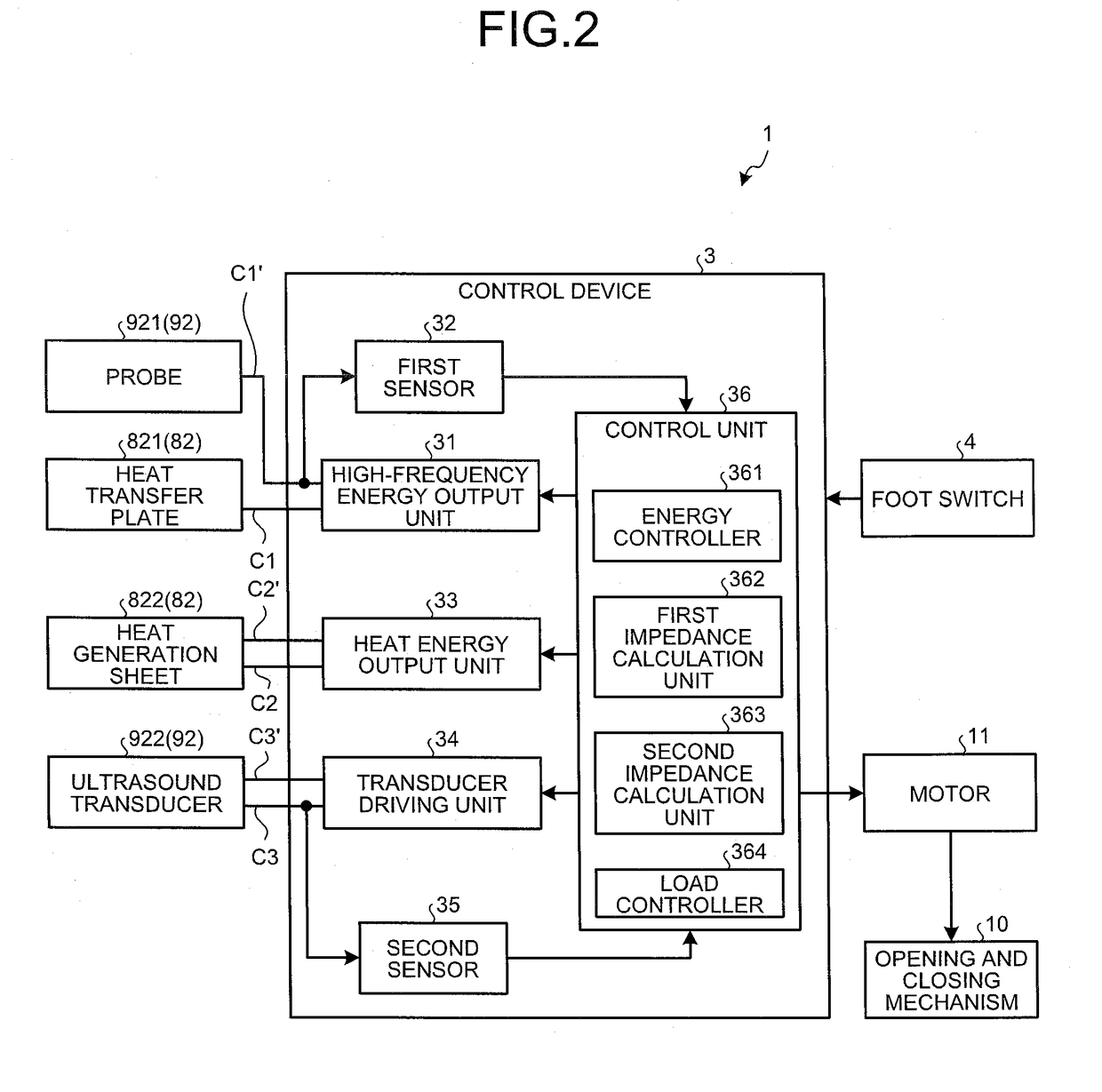
[0104]In other words, in the modification, the first and second sensors 32 and 35 as well as the first and second impedance calculation units 362 and 363 are omitted. In the connection control in the modification, Steps S4, S5, S7, and S8 are omitted, and Steps S14 and S15 are added, as illustrate...

second embodiment

Modification of Second Embodiment

[0147]In the second embodiment, application of ultrasound energy or heat energy may be started (the operation knob 51 may be switched from the restrictive state to the permissive state) when a predetermined time has elapsed, as in the modification (FIG. 7) of the first embodiment.

[0148]In the second embodiment, a notifying unit may be provided to notify the medical treatment device 1A that the operation knob 51 has been switched from the restrictive state to the permissive state.

[0149]Examples of the notifying unit include a light emitting diode (LED) for emitting light, a display for displaying messages, and a configuration for producing sound.

Other Embodiments

[0150]Hereinabove, the modes for carrying out the present invention have been described. However, the present invention should not be limited exclusively to the first and second embodiments and the modifications thereof.

[0151]In the first and second embodiments and the modifications thereof, t...


PUM


Abstract

A medical treatment device includes: a pair of holding members configured to grasp a target part to be connected in a body tissue; an energy application portion provided on at least one holding member of the pair of holding members, the energy application portion being configured to contact the target part when the target part is grasped by the pair of holding members to apply energy to the target part; and a processor including hardware. The processor is configured to cause the energy application portion to: apply high-frequency energy to the target part for a first period; apply ultrasound energy to the target part for a second period subsequent to the first period; and apply heat energy to the target part for a third period subsequent to the second period.

Description

CROSS REFERENCES TO RELATED APPLICATIONS[0001]This application is a continuation of PCT international application Ser. No. PCT / JP2015 / 055978, filed on Feb. 27, 2015 which designates the United States, incorporated herein by reference.BACKGROUND1. Technical Field[0002]The disclosure relates to a medical treatment device, a method for operating the medical treatment device, and a treatment method.2. Related Art[0003]In recent years, developments of medical treatment devices have been accelerated with which energy is applied to a target to be connected (hereinafter described as a target part) in a body tissue to connect the target part. Such medical treatment devices do not leave a physical object such as a stapler in a body, and therefore have an advantage that there are less adverse effects on a human body. On the other hand, connection strength thereof is weaker than that of the stapler or the like, and there are some target parts which cannot be connected depending on thickness the...

Claims


Application Information

Patent Timeline
IPC IPC(8): A61B18/14A61N7/02A61B18/00
CPCA61B18/1445A61B2018/00095A61N7/02A61B18/085A61B2018/00994
Inventor NARISAWA, MASATO
Owner OLYMPUS CORP
Why Eureka
Try Eureka