Hollow Needle Assembly

Inactive Publication Date: 2017-12-28
RAUMEDIC AG
View PDF3 Cites 3 Cited by
  • Summary
  • Abstract
  • Description
  • Claims
  • Application Information

AI Technical Summary

Benefits of technology

The invention aims to prevent liquid from transferring between different ducts in a hollow needle assembly, which can lead to issues like clogging and undesired foaming. This is achieved by using a sharp edge to separate the ducts and prevent liquid from coming into contact with the gas duct. The invention also includes an annular space and an air filter to further reduce the likelihood of clogging and prevent foreign bodies from entering the gas duct. Overall, the invention improves the functionality and reliability of the hollow needle assembly.

Problems solved by technology

Furthermore, a disadvantageous overflow of liquid into the gas duct under the action of gravitational force during injection is reduced.

Method used


Image

  • Hollow Needle Assembly
  • Hollow Needle Assembly
  • Hollow Needle Assembly

Examples


Embodiment Construction

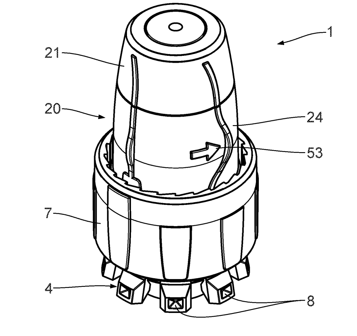
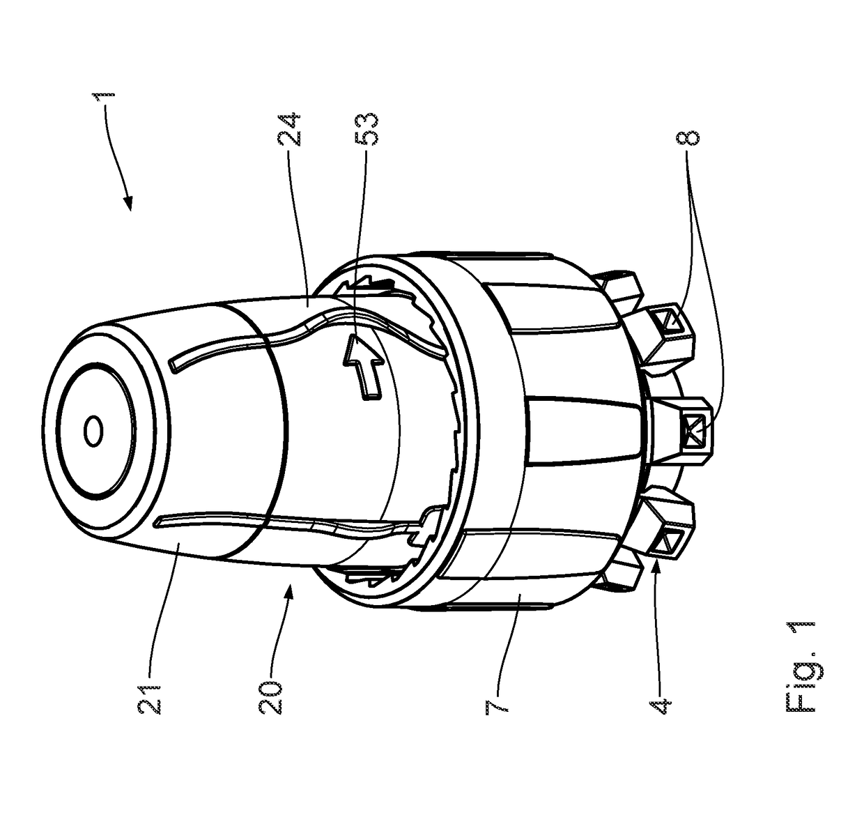
[0039]A first embodiment of an apparatus 1 for transferring a liquid between a storage container 2 (cf. FIG. 6) and at least one further storage container 3 (cf. FIG. 6) is described in the following text with reference to FIGS. 1 to 12. All the moulded parts of the transfer apparatus 1 are made of plastics material and are embodied in particular as injection-moulded parts.

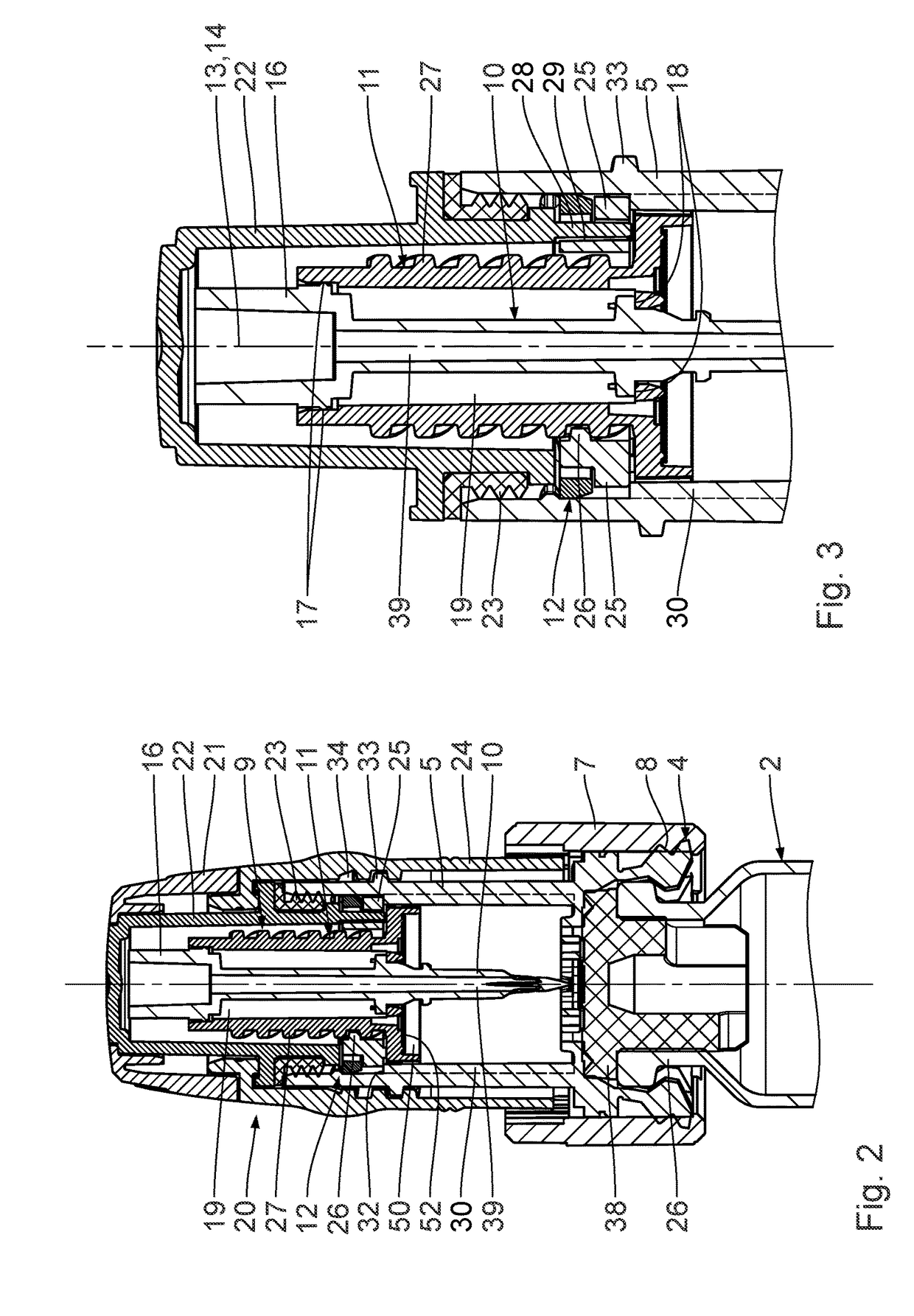
[0040]The transfer apparatus 1 has a sealing portion 4 for leaktight abutment of a main body 5 (cf. FIG. 2) of the transfer apparatus 1 against the storage container 2. The sealing portion 4 butts in this case against an elastomeric sealing plug of the storage container 2a, which will be described further in the following text. The sealing portion 4 engages in this case around a neck 6 of the storage container 2 (cf. FIG. 5). An external securing sleeve 7 of the transfer apparatus 1 serves to secure the sealing portion 4 in the sealing position thereof.

[0041]FIG. 1 shows the securing sleeve 7 in a transport positi...


PUM


Abstract

A hollow-needle assembly is part of a transfer apparatus that serves for transferring a liquid between a storage container and a further use container. The hollow-needle assembly has a hollow needle having a pointed needle end. A liquid duct for transporting liquid through the hollow needle and out of the latter leads out via at least one liquid-duct opening in the region of the free needle end. An aeration gas duct that likewise leads out via a gas-duct opening in the region of the free needle end serves for transporting gas through the hollow-needle assembly. Duct paths of the at least one liquid duct and of the at least one aeration gas duct extend separately from one another. The ducts lead out adjacently to one another axially along the hollow needle and in a manner offset from one another in the circumferential direction. A needle separating edge that extends in the longitudinal direction of the hollow needle extends between in each case one liquid-duct opening and an adjacent gas-duct opening in the circumferential direction. This results in reliable ventilation and venting of the storage container via the hollow needle when liquid is transferred.

Description

FIELD OF THE INVENTION[0001]The invention relates to a hollow-needle assembly for a transfer apparatus for transferring a liquid between a storage container and at least one further use container. Furthermore, the invention relates to a transfer apparatus having such a hollow-needle assembly and to a set having such a transfer apparatus and a storage container.BACKGROUND OF THE INVENTION[0002]A transfer apparatus having a hollow-needle assembly is known from WO 2011 / 088471 A1, from WO 2014 / 152249 A1, from WO 98 / 32411 A1, from U.S. Pat. No. 6,209,738 B1, from U.S. Pat. No. 6,537,263 B1, from U.S. Pat. No. 5,879,345 and from WO 2012 / 119225 A1.SUMMARY OF THE INVENTION[0003]It is an object of the present invention to develop a hollow-needle assembly is of the type mentioned at the beginning in such a way as to ensure reliable ventilation and venting of the storage container via the hollow needle when liquid is transferred.[0004]According to a first aspect, this object is achieved accord...

Claims


Application Information

Patent Timeline
IPC IPC(8): A61J1/20
CPCA61J1/2051A61J1/2096A61J1/2075A61J1/2055A61J1/2082A61J1/201
Inventor EICHELKRAUT, GEROFESTEL, TOBIASSKAPER, FRANKBAYER, MARTINMERHOLD, CHRISTOPH
Owner RAUMEDIC AG
Why Eureka
Try Eureka