Robust Safe Switch

a safe and switch technology, applied in the field of safe switches, can solve the problems of low “on”, low reliability, and worst, and achieve the effects of virtually no thermal loss, high reliability and energy efficiency, and low cos

Active Publication Date: 2017-12-28
MASTEN JR JAMES WILLIAM
View PDF1 Cites 5 Cited by
  • Summary
  • Abstract
  • Description
  • Claims
  • Application Information

AI Technical Summary

Benefits of technology

[0025]What is missing from the current repertoire of components to enable the Internet of Things is a cost-effective switch that is both highly reliable and energy efficient with virtually no thermal losses. Yet because this switch is by definition “remote” it must incorporate provisions to ensure the safety of equipment, lives and property.

Problems solved by technology

From the beginning of controlled electrical switching, arc pitting and the wear of switch contact points has been a pervasive issue that actually created significant job opportunities over many decades.
But these devices, at best, have about a 1.5 Volt drop across the device when switched on.
In today's environmentally sensitive market, 30 Watts per switch is a terrible waste.
The contact points have to be specifically designed to be “self cleaning,” in which case they are designed to wear out but maintain a low “on” resistance; or they are dramatically over-built in anticipation of wear.
In either case, mechanical relays have a significant wear rate.

Method used


Image

  • Robust Safe Switch
  • Robust Safe Switch
  • Robust Safe Switch

Examples


Embodiment Construction

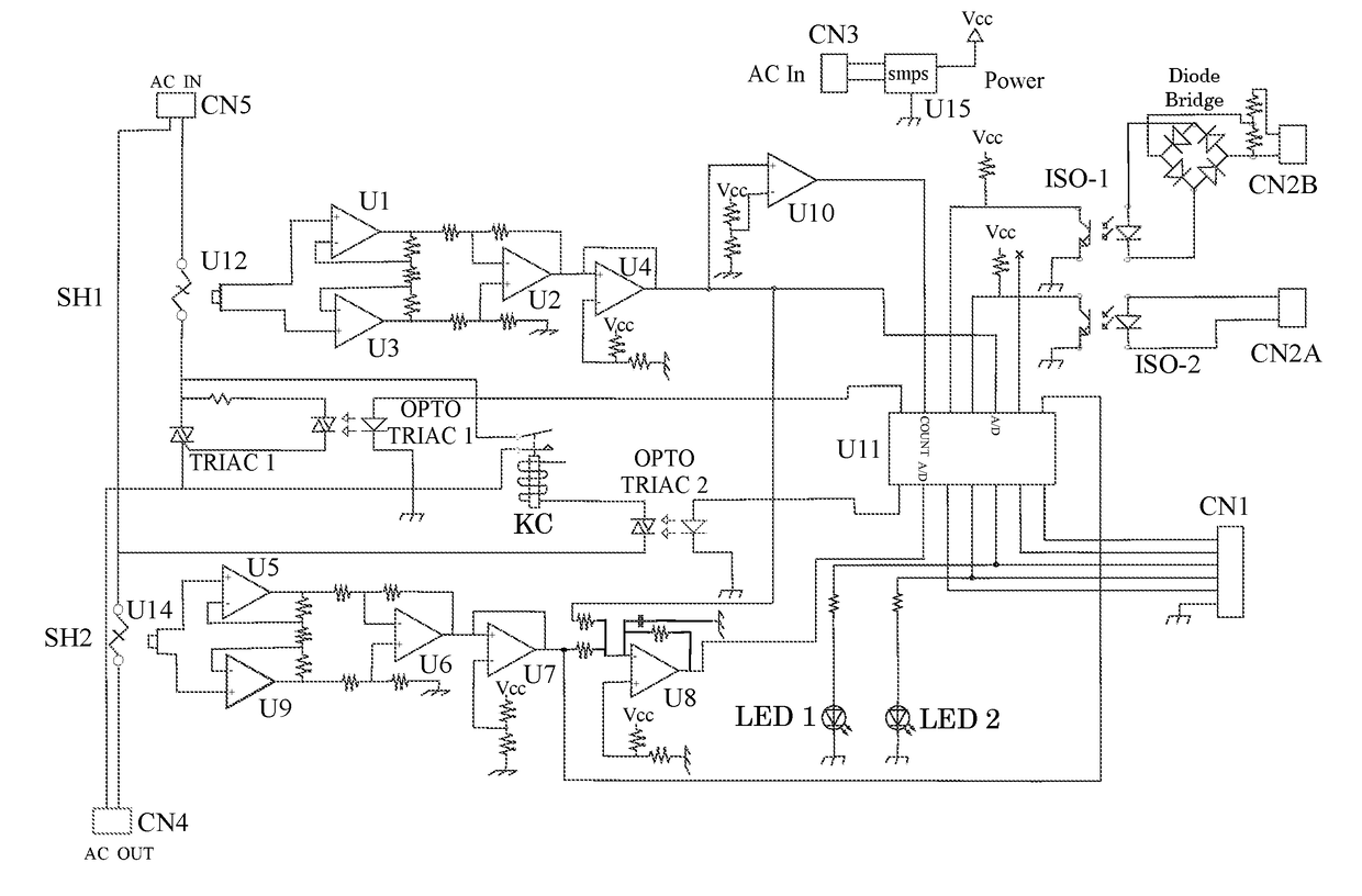
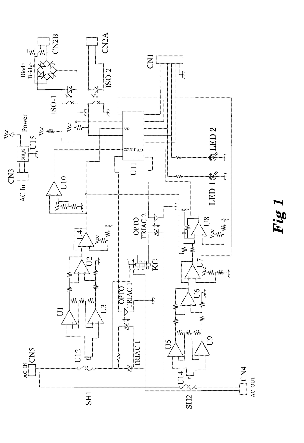
[0037]The Robust Safe Switch circuit performs several separate functions simultaneously using a hybrid mix of analog and digital circuitry. The following description is notional, or an example. The circuit could be implemented with a variety of circuit components able to provide the method functionality.

[0038]ISO-1 and ISO-2 are open collector type opto-isolators that enable the circuit to be controlled by virtually any type of device that can source a minimum amount of current at a minimum voltage. The circuit can be configured on the inputs to connector CN2A to operate as driven by an AC / Neutral input or to be driven by a separate DC source CN2B. ISO-1 and ISO-2 completely isolate the circuit from the devices providing the driving current to CN2B and CN2A, respectively.

[0039]U15 is a highly efficient Switch Mode Power Supply (smps) providing DC power from the AC Line voltage, as presented in FIG. 1 to be 120-240 Volts AC. Such an smps power supply could be created using an integra...


PUM


Abstract

The Robust Safe Switch and Control Device is an “Internet of Things” end effecter that provides a minimally dissipating, robust switch tightly integrated with circuit, life and property automated safety features. The device enables extended sensing and monitoring capabilities that enable the effective management of the “Internet of Things.”

Description

BACKGROUND OF THE INVENTION[0001]From the beginning of controlled electrical switching, arc pitting and the wear of switch contact points has been a pervasive issue that actually created significant job opportunities over many decades. With the advent of alternating current, point wear was at least somewhat normalized between the two points. And with the development of more powerful electrical machines switching apparatus became remote to the actual user as the economies of smaller wire and small currents were used to remotely switch much larger electrically activated switches.[0002]For many decades, the salvation of remote switching of resistive and especially inductive loads was the mercury-wetted contact relay. The resurfacing of the contacts with every mechanical action provided a switching lifetime rated in the tens of millions of cycles; but recent environmental concerns have eliminated the use of mercury in routine industrial and commercial devices and more so in the househol...

Claims


Application Information

Patent Timeline
Patent Type & Authority Applications(United States)
IPC IPC(8): H03K17/13G01R31/02G01R19/165H02H3/08H02H1/00
CPCH03K17/136H02H3/08G01R19/165H02H1/0015G01R31/025H02H1/0007G01R31/3278G01R31/52H02H3/044H02H3/33G01R31/50
Inventor MASTEN, JR., JAMES WILLIAM
Owner MASTEN JR JAMES WILLIAM
Why Eureka
Try Eureka