Apparatus and method for producing a rubber caterpillar track with tensile members

Inactive Publication Date: 2018-01-04
CONTITECH TRANSPORTBANDSYSTEME GMBH
View PDF4 Cites 0 Cited by
  • Summary
  • Abstract
  • Description
  • Claims
  • Application Information

AI Technical Summary

Benefits of technology

The present invention aims to provide an apparatus and method for producing rubber caterpillar tracks with tensile members. This invention can produce rubber caterpillar tracks with tensile members easily and inexpensively without the possibility of a displacement of the tensile members during the production process. Additionally, the invention can reduce the displacement of the tensile members, which leads to an improvement in the durability and longevity of the rubber caterpillar track. The invention also uses shaped elements to produce the external teeth of the rubber caterpillar track, which is more easily and less expensively than pressing the outside profiling out of the unvulcanized material of the body of the rubber caterpillar track. The use of shaped elements can also reduce the pressing pressure and can therefore perform vulcanization in an autoclave, which reduces production costs. The invention further includes the use of radially movable outer mold segments that compensate for manufacturing differences between the individual shaped elements and prevents movements in the elastomer material other than in the radial direction.

Problems solved by technology

A disadvantage of the two above-described methods is that the external contour of the rubber caterpillar track is formed by pressing of the unvulcanized body of the rubber caterpillar track.
Since the tensile members are however arranged in the unvulcanized body of the rubber caterpillar track and the pressing of the unvulcanized material causes the material to be deformed almost exclusively in the radially outer region of the body of the rubber caterpillar track, this can result in the tensile members being displaced out of their original arrangement.
This can lead to tearing of the rubber caterpillar track and reduce the service life of the rubber caterpillar track.

Method used


Image

  • Apparatus and method for producing a rubber caterpillar track with tensile members
  • Apparatus and method for producing a rubber caterpillar track with tensile members
  • Apparatus and method for producing a rubber caterpillar track with tensile members

Examples


Embodiment Construction

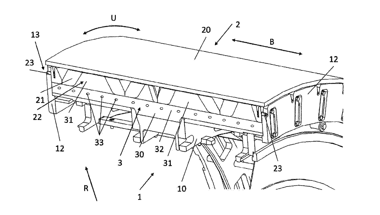
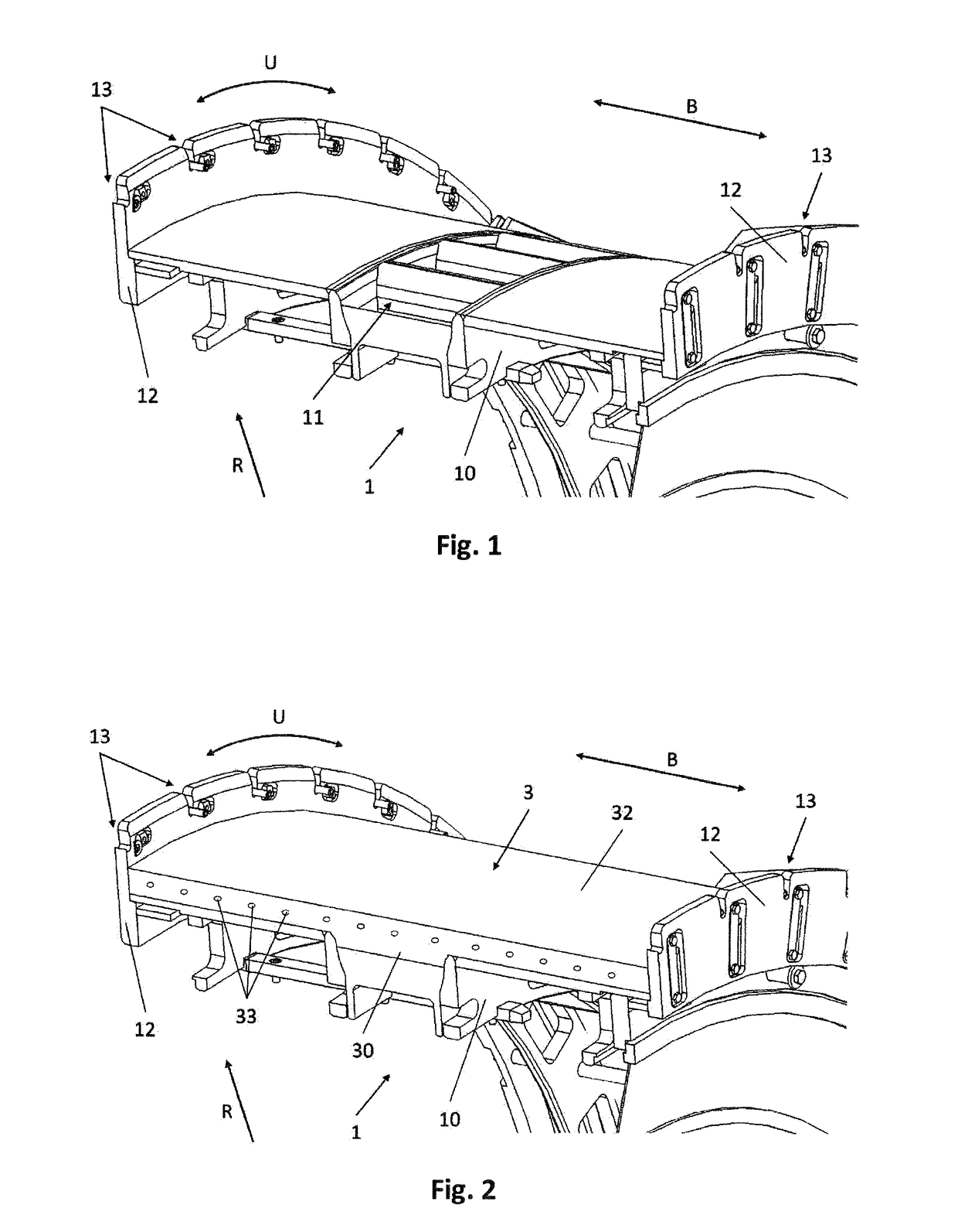
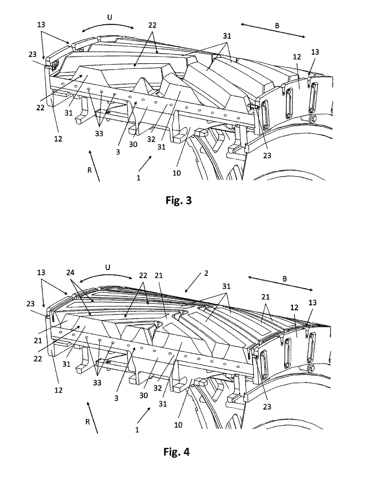
[0035]The device has an inner mold 1 which is of cylindrical form and which extends over a width B and in a circumferential direction U. The inner mold 1 has a cylindrical mandrel 10, laterally on the outer surface of which in a radial direction R there is formed, in the center, a multiplicity of apertures or recesses 11 for receiving unvulcanized shaped elements for internal teeth 30 of a rubber caterpillar track 3. The radial outer surface of the mandrel 10 is delimited laterally in terms of width B by lateral delimitations 12 which each have radial slots 13.

[0036]The device furthermore has an outer mold 2 which has a multiplicity of outer mold segments 21 which together form a cylindrical arrangement. The outer mold segments 21 are held from radially outside by a deformable jacket 20 and can be pressed together in a radially inward direction by the jacket. Each outer mold segment 21 has a recess 22 which corresponds to the contour of an unvulcanized shaped element for an external...


PUM


Abstract

An apparatus for producing a rubber caterpillar track with tensile members has a cylindrical internal shape for forming the inside contour of the rubber caterpillar track, wherein the internal shape has a cylindrical dome which, in the circumferential direction (U) on its radial outer side, has a plurality of recesses for accommodating unvulcanized shaped elements for internal teeth, and has a cylindrical external shape for forming the outside contour of the rubber caterpillar track, wherein the external shape has a plurality of external shape segments in the circumferential direction (U). The external shape segments each have a recess on their radial inner side for accommodating an unvulcanized shaped element for external teeth. The invention further relates to a method for producing a rubber caterpillar track with tensile members.

Description

CROSS REFERENCE TO RELATED APPLICATIONS[0001]This application is a continuation application of international patent application Ser. No. PCT / EP2016 / 050636, filed Jan. 14, 2016 designating the United States and claiming priority from German application 10 2015 205 071.8, filed Mar. 20, 2015, and the entire content of both applications is incorporated herein by reference.FIELD OF THE INVENTION[0002]The invention relates to a device for producing a rubber caterpillar track with tensile and to a method for producing a rubber caterpillar track using a device of this type.BACKGROUND OF THE INVENTION[0003]Known drive mechanisms for land vehicles include, inter alia, caterpillar tracks. These may be utilized not only in the military sector but also for agricultural vehicles and for other vehicles for transportation on rough terrain. Caterpillar tracks commonly have inwardly projecting tooth elements on their inside, preferably in the center, via which tooth elements the caterpillar track ca...

Claims


Application Information

Patent Timeline
IPC IPC(8): B29D29/00B29C43/46B29C35/02
CPCB29D29/00B29C43/46B29C35/0277B29D29/085
Inventor HUELS, ACHIMBEHRENS, CARSTEN
Owner CONTITECH TRANSPORTBANDSYSTEME GMBH
Why Eureka
Try Eureka