Tubing Hanger Apparatus, System and Methods

a technology of apparatus and hangers, applied in the direction of sealing/packing, earth-moving drilling, wellbore/well accessories, etc., can solve the problems of compromising the fluid integrity of the interior flowpath, preventing the proper function of the device, and affecting the safety of the devi

Active Publication Date: 2018-01-04
PEAK COMPLETION TECH
View PDF0 Cites 3 Cited by
  • Summary
  • Abstract
  • Description
  • Claims
  • Application Information

AI Technical Summary

Benefits of technology

[0007]Embodiments of the present disclosure include hanger devices which do not have penetrations through the device wall because such devices do not require communication of force, such as fluid pressure or mechanical force, through the wall of the device in order to actuate. Embodiments according to the disclosure herein may actuate and set based in part on the distance below surface and / or location of the hanger within the host tubing. Still further embodiments may eliminate the use of teeth or other devices that penetrate the wall of the tubing into which the device is set.

Problems solved by technology

Seals may fail, however, compromising the fluid integrity of the interior flowpath and in some cases preventing the proper function of the devices.
Prior art devices also comprise slips that penetrate into, causing at least some damage to, the wall of tubing into which the device is suspended.

Method used


Image

  • Tubing Hanger Apparatus, System and Methods
  • Tubing Hanger Apparatus, System and Methods
  • Tubing Hanger Apparatus, System and Methods

Examples


Embodiment Construction

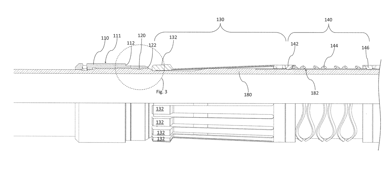
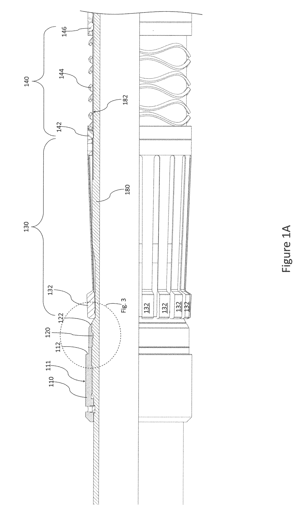
[0019]FIGS. 1A and 1B illustrate one embodiment according to the present disclosure in the unactuated or run in position. The illustrated embodiment comprises tubing 180 with a hanging section and an actuation section arranged on its outer surface. The hanging section comprises a top sub 110, the top sub 110 having a hanging shoulder 112, cone 120 with angular surface 122 and collet 130 having a plurality of latches 132 positioned adjacent to angular surface 122.

[0020]The actuation section may comprise a spring element 140, a piston 160 and a lock such as lock ring 152 in lock housing 150. Spring assembly 140 may be adjacent to and engage collet 130. Spring assembly 140 may comprise a spring element 144 and end rings 142, 146. End rings 142, 146 may be attached to the ends of spring element 144 and may engage a groove 182, such as in tubing 180, such that spring assembly 140 resists rotation.

[0021]Piston 160 slidably engages tubing 180. Seal stacks 166, 168 prevent fluid communicati...


PUM


Abstract

Hangers and related tools which actuate without fluid or mechanical communication between the interior of the tool and its exterior are disclosed. Devices as disclosed herein may include a piston for applying actuating force based on the fluid pressure outside of the tool. The piston may be fixed to a tubing wall or other body of the tool with a shear element to prevent the tool from actuating until a certain pressure is applied to piston, such as by the static pressure of wellbore fluid at a certain depth, by pressure applied to the annulus from surface, or a combination thereof. Actuation of the tool may cause latches to expand outwardly to engage a latch receptacle fixed in or along the host tubing or such actuation may lead to other hanging members, such as slips, to engage the host tubing wall in order to suspend the hanging string therein.

Description

CROSS REFERENCE TO RELATED APPLICATIONS[0001]This application claims the benefit of U.S. Provisional Patent Application Ser. No. 62 / 343,470 titled “Tubular Connector Device and Methods”, filed on May 31, 2016, the entirety of which is incorporated herein by reference.STATEMENT REGARDING FEDERALLY SPONSORED RESEARCH OR DEVELOPMENT[0002]Not applicable.BACKGROUND[0003]The present disclosure relates to apparatuses, systems and methods for suspending tubing in a well or wellbore. Certain embodiments according to the present disclosure may permit actuation of the apparatus without applying fluid pressure or fluid flow, may permit systems or apparatuses to operate without teeth or other elements that bite into the casing wall, may set automatically upon reaching the desired location, combinations of certain or all of the foregoing, and / or provide other benefits.[0004]Devices for suspending tubing, such as a tubing string, within sections of a well or wellbore are known in the art. Such dev...

Claims


Application Information

Patent Timeline
Patent Type & Authority Applications(United States)
IPC IPC(8): E21B23/10
CPCE21B23/10E21B33/04
Inventor GODFREY, MATTHEW M.FITZHUGH, BRYANMUSCROFT, WILLIAM SLOANE
Owner PEAK COMPLETION TECH
Why Eureka
Try Eureka