Infusion device with releasable fluid connector

a technology of fluid connector and infusion device, which is applied in the direction of catheters, infusion needles, other medical devices, etc., can solve the problems of difficult to grasp, large and/or rigid needle guards, and difficulty in balancing the force required to disconnect tubing, so as to improve the infusion device, prevent accidental removal of catheters, and improve the effect of infusion

Active Publication Date: 2018-01-11
BECTON DICKINSON & CO
View PDF9 Cites 1 Cited by
  • Summary
  • Abstract
  • Description
  • Claims
  • Application Information

AI Technical Summary

Benefits of technology

The present invention provides improved infusion devices that address concerns related to accidental removal of the catheter during infusion. The device balances the force required for separation and retention, allowing efficient infusion while preventing accidental removal. The fluid connector includes a fluid path and a displaceable connector latch that securely attaches the fluid connector to the base in multiple rotational positions. This ensures the fluid connector remains secure during use.

Problems solved by technology

In some uses, however, it may be larger and / or rigid.
With such devices, however, there are concerns over the difficulty of balancing the force required to disconnect the tubing without pulling the catheter from the user's skin versus having enough retention force to secure the infusion components for everyday infusion.
These needle guards, however, are often very small and may be difficult to grasp, particularly for people with impaired dexterity.
Further, with such needle guards, once the coefficient of static friction is overcome, the guard may separate quickly, without providing an opportunity for a user to modify the applied force and potentially resulting in a needle-stick injury.
Further, there is a risk that the needle guard can contact the needle during removal, potentially dulling the cannula or introducer needle.

Method used


Image

  • Infusion device with releasable fluid connector
  • Infusion device with releasable fluid connector
  • Infusion device with releasable fluid connector

Examples


Embodiment Construction

[0085]Reference will now be made in detail to an embodiment of the present invention, which is illustrated in the accompanying drawings, wherein like reference numerals refer to like elements throughout. The embodiment described herein exemplifies, but does not limit, the present invention by referring to the drawings. As will be understood by one skilled in the art, terms such as up, down, bottom, top, proximal, and distal are relative, and are employed to aid illustration, but are not limiting.

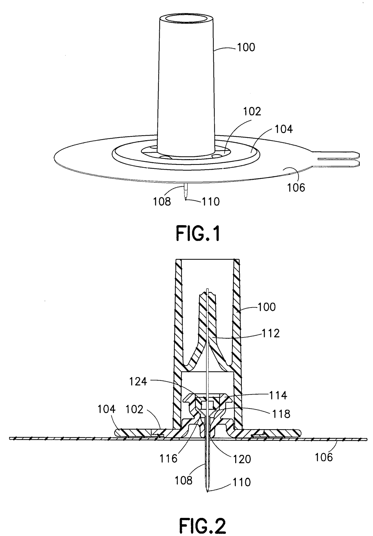
[0086]FIG. 1 illustrates an exemplary embodiment of an infusion set comprising an introducer needle hub 100 engaged with a base 102. The base 102 engages a flexible disc 104 positioned between the base 102 and a user. The flexible disc 104 provides improved comfort and mobility of the device because it moves with the user during physical activity while minimizing contact of the rigid portions of the base 102 with the user. The flexible disc 104 is attached to an adhesive patch or pad 106 hav...


PUM


Abstract

An infusion set system includes a base and a fluid connector removably coupleable thereto. The fluid connector includes a fluid path portion and at least one connector latch displaceably connected to the fluid path portion and displaceable to a latching position in which at least a portion of the connector latch extends into the fluid path portion, which includes a cannula extending from a top interior surface thereof, and a plurality of internal sidewalls corresponding to at least two of a plurality of flat side surfaces of at least one of a base section and a base latch, thereby facilitating connection between the base and the fluid connector in a plurality of discrete rotational connecting positions. When the fluid connector is locked to the base, the at least one connector latch engages a base latching portion of the base and restricts proximal displacement of the fluid connector.

Description

CROSS-REFERENCE TO RELATED APPLICATIONS[0001]This application is a continuation of U.S. patent application Ser. No. 14 / 362,104, filed on May 30, 2014, which is the U.S. national stage of International Application No. PCT / US12 / 68632, filed on Dec. 7, 2012, which claims priority under 35 USC §119(e) from U.S. Provisional Application Nos. 61 / 568,074, 61 / 692,985, and 61 / 719,755 filed on Dec. 7, 2011, Aug. 24, 2012, and Oct. 29, 2012 respectively. The disclosure of each of these applications is incorporated herein by reference in its entirety.FIELD OF THE INVENTION[0002]The present invention relates generally to infusion devices, and more particularly, to subcutaneous infusion devices to be used in conjunction with an infusion pump in the infusion of insulin and other medicaments.BACKGROUND OF THE INVENTION[0003]One mode of insulin infusion treatment includes infusion pump therapy via a catheter, needle or other type of cannula. Infusion pumps offer the advantages of continuous infusion ...

Claims


Application Information

Patent Timeline
Patent Type & Authority Applications(United States)
IPC IPC(8): A61M39/10A61M5/158
CPCA61M2005/1586A61M2005/1585A61M39/1055A61M5/158A61M25/0606A61M2005/1581A61M39/045A61M2005/1587A61M5/3202A61M5/3213A61M2039/0072A61M2207/00A61M5/14248A61M2039/0036B29C45/1615B29C45/14B29C45/16B29C45/1657B29C45/14344
Inventor SONDEREGGER, RALPHMARSH, RONALDHWANG, CHARLESRICHARDS, STEPHENPOLITIS, VICTORHORVATH, JOSHUAGLACE, BENJAMINSULLIVAN, JAMESLAMBERT, RYANVENDITTO, GREGORYBENE, ERIC
Owner BECTON DICKINSON & CO
Why Eureka
Try Eureka