Internal combustion engine with rotor having offset peripheral surface

a peripheral surface, internal combustion technology, applied in combustion engines, machines/engines, pump components, etc., can solve the problems of limiting the available compression ratio, expansion ratio and/or minimum volume available for combustion

Active Publication Date: 2018-01-11
PRATT & WHITNEY CANADA CORP
View PDF5 Cites 3 Cited by
  • Summary
  • Abstract
  • Description
  • Claims
  • Application Information

AI Technical Summary

Problems solved by technology

In some instances, the maximum desirable recess volume may limit the available c

Method used


Image

  • Internal combustion engine with rotor having offset peripheral surface
  • Internal combustion engine with rotor having offset peripheral surface
  • Internal combustion engine with rotor having offset peripheral surface

Examples


Embodiment Construction

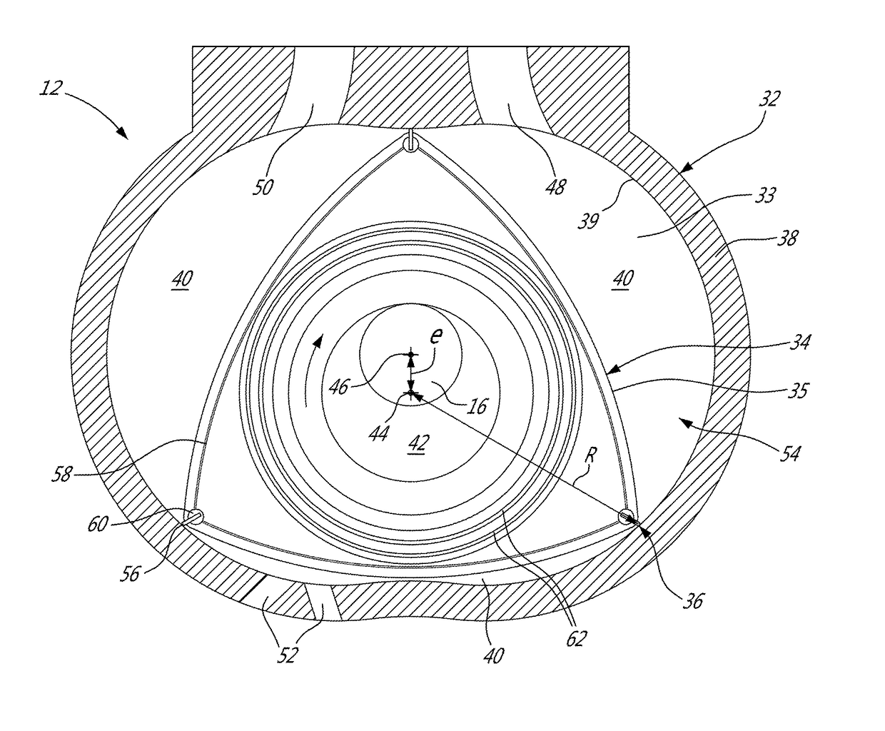
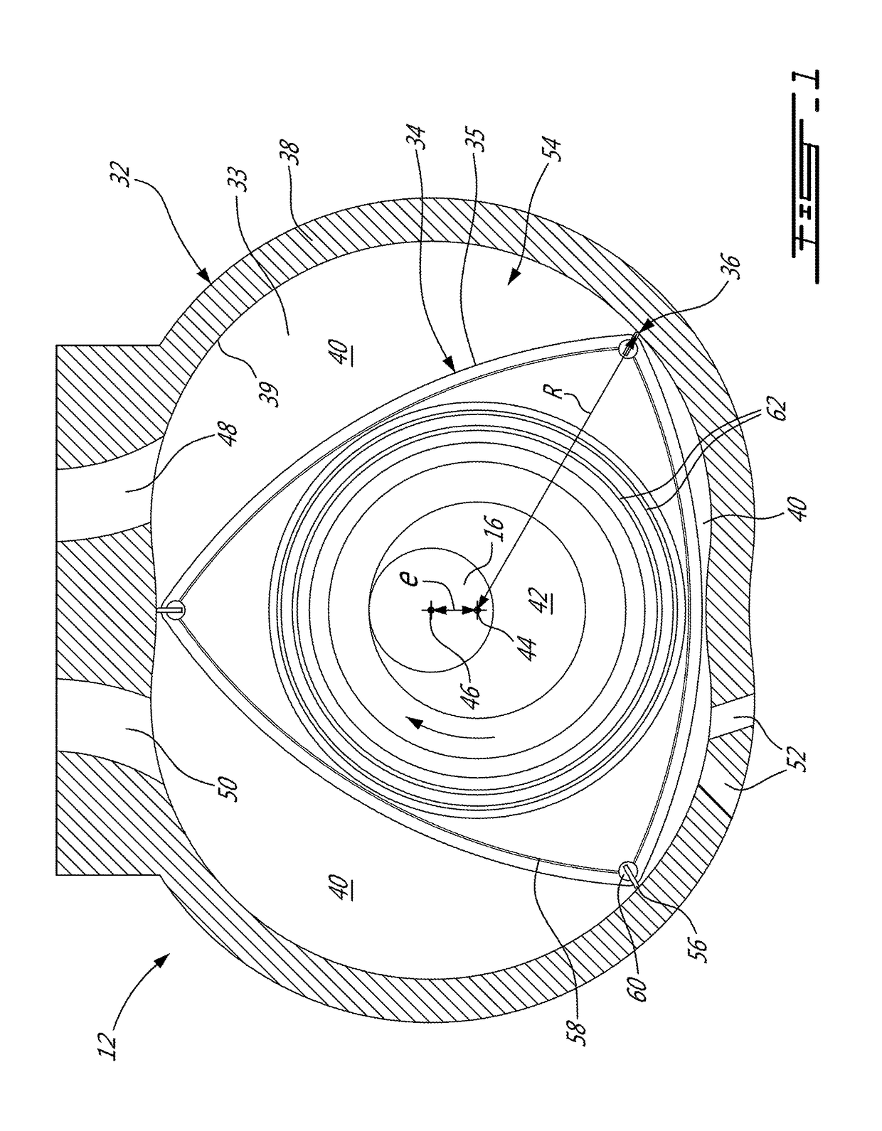
[0012]FIG. 1 illustrates an example of a rotary intermittent internal combustion engine 12 of the type known as a Wankel engine. It is understood that the configuration of the engine 12, e.g. placement of ports, number and placement of seals, etc., may vary from that of the embodiment shown.

[0013]The engine 12 comprises a housing 32 defining a rotor cavity 33 having a profile defining two lobes. The housing 32 has a peripheral wall 38 extending between two axially spaced apart end walls 54 to enclose the rotor cavity 33. A rotor 34 is received within the rotor cavity 33. The rotor 34 has a peripheral outer surface 35 defining three circumferentially-spaced apex portions 36, and a generally triangular profile with outwardly arched sides. The apex portions 36 are in sealing engagement with the peripheral inner surface 39 of the rotor cavity 33, defined by the peripheral wall 38 of the housing 32, to form and separate three working chambers 40 of variable volume between the rotor 34 an...


PUM


Abstract

A rotary engine where the rotor cavity has a peripheral inner surface having a peritrochoid configuration defined by a first eccentricity and the rotor has a peripheral outer surface having a peritrochoid inner envelope configuration defined by a second eccentricity larger than the first eccentricity. Also, a rotary engine where the rotor cavity has a peripheral inner surface having a peritrochoid configuration defined by an eccentricity, and a rotor with a peripheral outer surface between adjacent ones of the apex portions being inwardly offset from a peritrochoid inner envelope configuration defined by the eccentricity. The engine may have an expansion ratio with a value of at most 8. The rotary engine may be part of a compound engine system.

Description

TECHNICAL FIELD[0001]The application relates generally to rotary internal combustion engines and, more particularly, to rotors for such engines.BACKGROUND OF THE ART[0002]Wankel rotary engines typically include recesses in the rotor flanks, and the recess volume is used to adjust the compression and expansion ratios of the engine as well as the minimum volume available for combustion. In some instances, the maximum desirable recess volume may limit the available compression ratio, expansion ratio and / or minimum volume available for combustion.SUMMARY[0003]In one aspect, there is provided a rotary engine comprising: a housing defining a rotor cavity with a peripheral inner surface having a peritrochoid configuration defined by a first eccentricity eH; and a rotor rotationally received in the rotor cavity, the rotor having a peripheral outer surface defining a plurality of circumferentially spaced apex portions each including an apex seal biased away from the peripheral outer surface ...

Claims


Application Information

Patent Timeline
IPC IPC(8): F01C21/08F02B37/00F02B53/08F01C1/22F02B53/00
CPCF01C21/08F02B53/08F02B2053/005F01C1/22F02B37/00F01C21/106F04C2250/20F04C2250/301Y02T10/12
Inventor GAUVREAU, JEAN-GABRIELGAGNON-MARTIN, DAVIDJULIEN, ANDRE
Owner PRATT & WHITNEY CANADA CORP
Why Eureka
Try Eureka