Apparatus and method for mapping frame buffers to logical displays

a frame buffer and display technology, applied in the field of display systems, can solve the problem that typical systems may not necessarily be able to support the same from a system architecture perspective, and achieve the effects of reducing computation, reducing power consumption, and reducing the number of involved frame buffers

Inactive Publication Date: 2018-01-11
FUTUREWEI TECH INC
View PDF4 Cites 4 Cited by
  • Summary
  • Abstract
  • Description
  • Claims
  • Application Information

AI Technical Summary

Benefits of technology

[0014]To this end, in some optional embodiments, one or more of the foregoing features of the aforementioned apparatus, computer program, and / or method may provide flexible support to embodiments involving multiple physical displays since each logical display can be mapped to one or more physical displays. Further, each logical display may independently perform compositions according to its own parameters (e.g. frame rate, etc.). By this feature, a number of compositions may be reduced and, for each composition, a number of involved frame buffers may also be reduced. In one embodiment, such reduction in compositions may translate into a reduction in computations with a corresponding reduction in power usage. In addition, one or more of the foregoing features may also reduce a necessary memory footprint, reduce a system response time, and allow a different set of image processing features to be independently applied to different logical displays and a corresponding one or more physical displays. It should be noted that the aforementioned potential advantages are set forth for illustrative purposes only and should not be construed as limiting in any manner.

Problems solved by technology

Specifically, in a situation where: 1) applications require the display of contents on different physical displays and / or 2) an application requires one part of a frame buffer to be displayed on a first physical display and another part to be displayed on a different physical display, typical systems may not necessarily be able to support the same from a system architecture perspective.

Method used


Image

  • Apparatus and method for mapping frame buffers to logical displays
  • Apparatus and method for mapping frame buffers to logical displays
  • Apparatus and method for mapping frame buffers to logical displays

Examples


Embodiment Construction

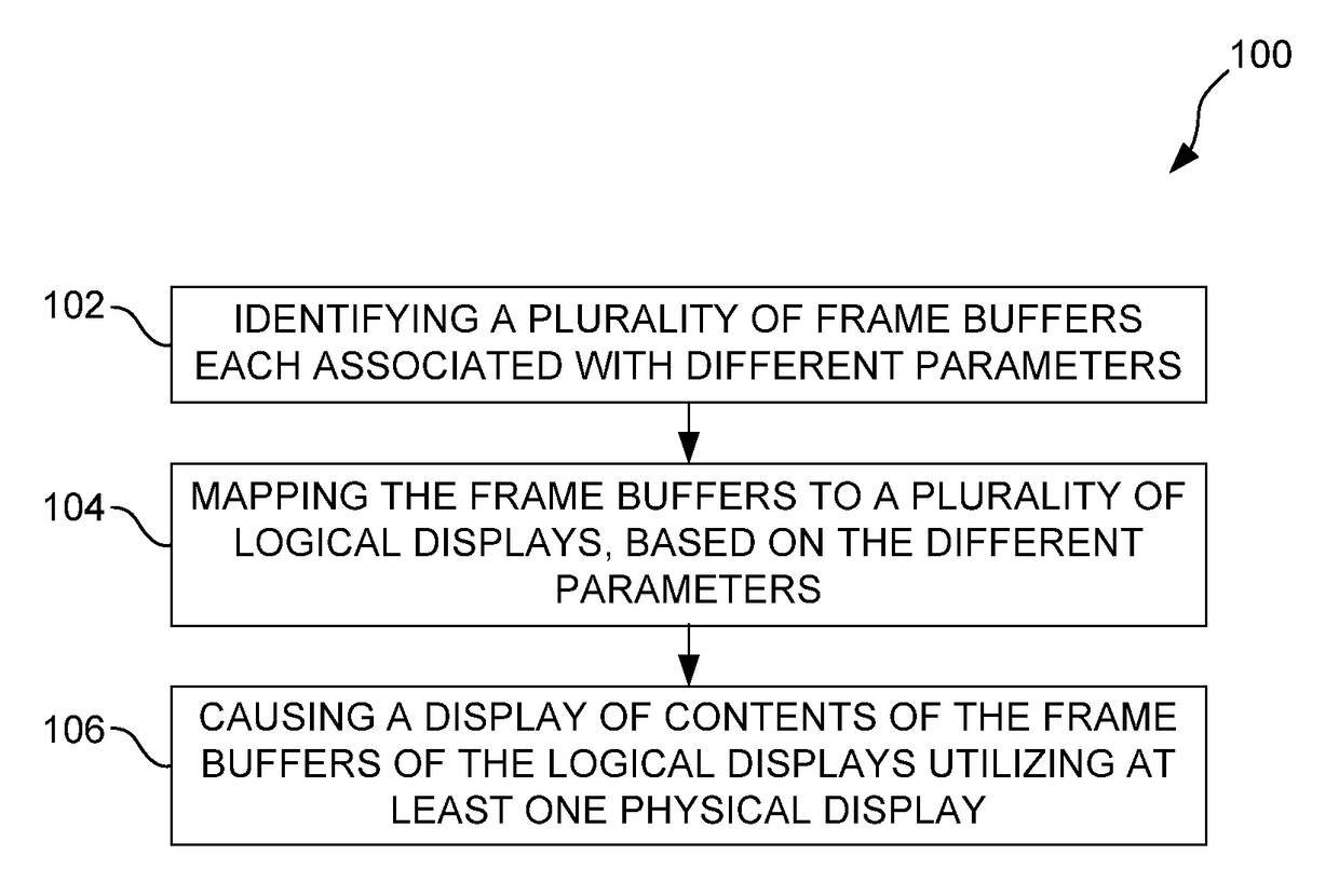
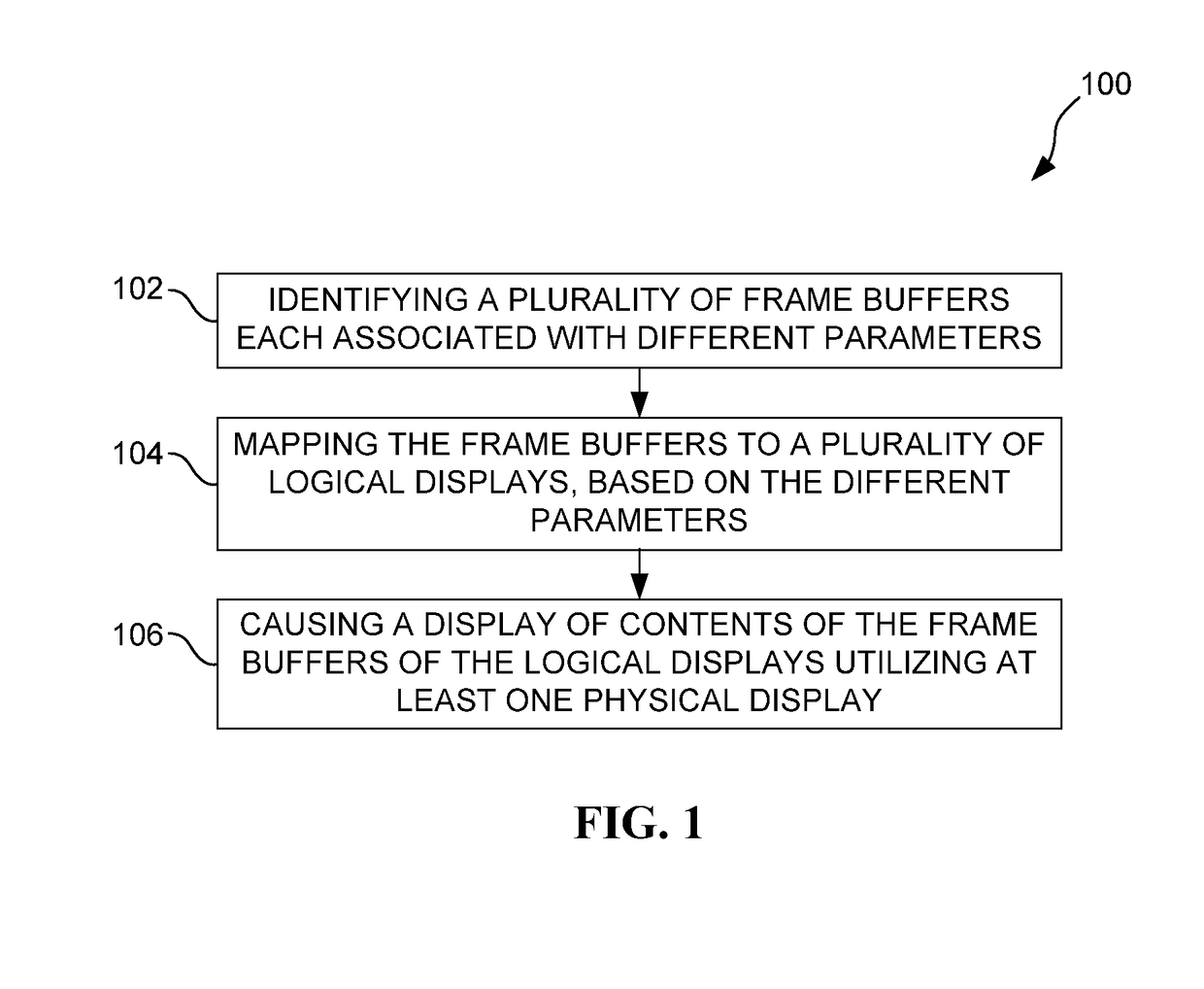
[0023]FIG. 1 illustrates a method 100 for mapping frame buffers to a plurality of logical displays, in accordance with one embodiment. In the context of the present description, such frame buffers may include any logical and / or physical memory that are configured for including contents such as pixel information, frame information, display information, and / or other information generated and / or used for processing in advance of a presentation thereof via a display. Non-exhaustive examples of the aforementioned contents may include, but is not limited to color / lighting values, geometric / position values, and / or any other data, for that matter.

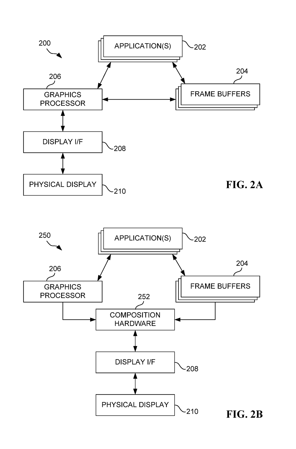
[0024]In one possible embodiment, the frame buffers may each be associated with at least one of a plurality of different applications that serve to generate the contents of the frame buffers. Further, in different optional embodiments, the frame buffers may be implemented utilizing any desired memory including, but not limited to general purpose me...


PUM


Abstract

A processing device, computer program, and method are provided for mapping frame buffers to a plurality of logical displays. A plurality of frame buffers are identified which are each associated with different parameters. The frame buffers are mapped to a plurality of logical displays, based on the different parameters. A display of contents of the frame buffers mapped to the logical displays is caused utilizing at least one physical display.

Description

RELATED APPLICATION(S)[0001]The present application claims priority to a provisional application filed on Jul. 7, 2016, under Application Ser. No. 62 / 359,651, which is incorporated herein by reference in its entirety for all purposes.FIELD OF THE INVENTION[0002]The present invention relates to display systems, and more particularly to display sub-systems that perform processing in advance of display.BACKGROUND[0003]Typically, devices are equipped with one main physical display. Some devices, however, have one smaller secondary display. In use, for a device with a main physical display, each application requests a frame buffer to hold contents (e.g. image, frame, etc.) to be displayed on the main physical display, and updated contents are submitted to a display sub-system. The display sub-system, in turn, takes such filled frame buffers, and composes a final display image, and sends the composited contents to the appropriate physical display.[0004]The foregoing architecture exhibits ...

Claims


Application Information

Patent Timeline
Patent Type & Authority Applications(United States)
IPC IPC(8): G09G5/395G06F3/14G06T1/60G06T1/20
CPCG09G5/395G06F3/1423G06T1/20G09G2360/18G06T1/60G09G5/14G09G5/397G09G2340/0435G09G2320/0673G09G2320/0686G09G2340/0407G09G2340/0428
Inventor HU, FANGQIZHENG, PINGFANGYANG, TONGZENGZHONG, HAIBOJIA, ZHIPING
Owner FUTUREWEI TECH INC
Why Eureka
Try Eureka