Automated vehicle radar system with auto-alignment for azimuth, elevation, and vehicle speed-scaling-error

a vehicle radar and automatic alignment technology, applied in the field of radar systems, can solve problems such as inability to compensa

Active Publication Date: 2018-01-25
APTIV TECH LTD
View PDF0 Cites 21 Cited by
  • Summary
  • Abstract
  • Description
  • Claims
  • Application Information

AI Technical Summary

Problems solved by technology

Alignment procedures performed when the host-vehicle is assembled are not able to compensate for pitch or elevation errors caused by heavy cargo and yaw or azimuth errors caused by miss-alignment of the wheels or chassis of the host-vehicle which may cause ‘crabbing’ or ‘dog-tracking’ by the host-vehicle while traveling.

Method used


Image

  • Automated vehicle radar system with auto-alignment for azimuth, elevation, and vehicle speed-scaling-error
  • Automated vehicle radar system with auto-alignment for azimuth, elevation, and vehicle speed-scaling-error
  • Automated vehicle radar system with auto-alignment for azimuth, elevation, and vehicle speed-scaling-error

Examples


Embodiment Construction

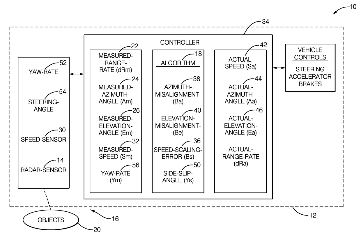
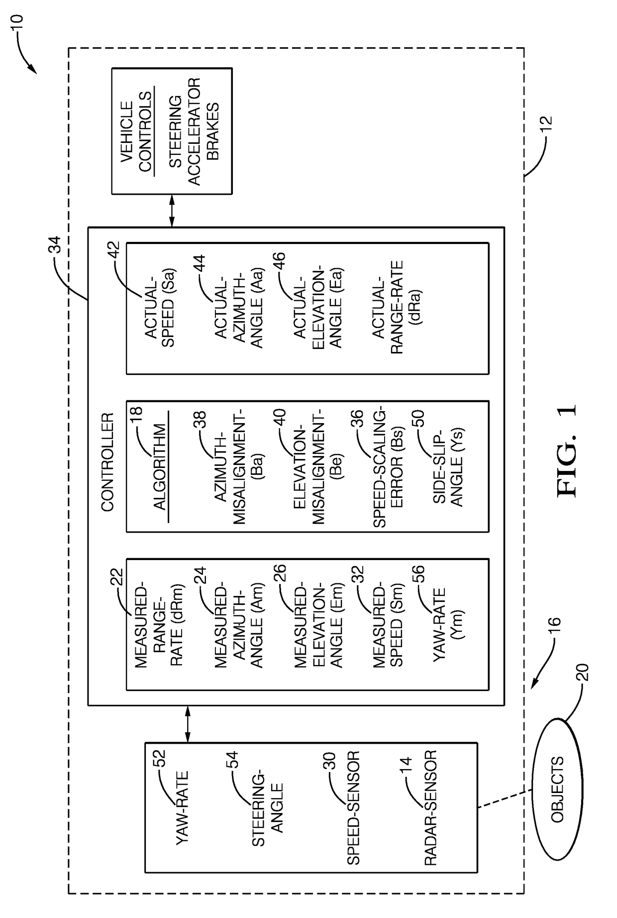
[0014]FIG. 1 illustrates a non-limiting example of a radar system 10, hereafter referred to as the system 10. The system 10 is generally suitable for use in an automated vehicle, a host-vehicle 12 for example, and is equipped with an auto-alignment feature for aligning a radar-sensor 14 with a reference frame established by the body of the host-vehicle 12. The performance and utility of an automotive radar system is improved if the radar target tracker algorithm, hereafter referred to as the tracker, has knowledge of (i.e. is programmed or calibrated with) the actual angular mounting orientation of the radar-sensor relative to the field-of-view 16 observed by the radar-sensor and / or the vehicle or structure on which the radar-sensor is mounted. Advantageously, this is accomplished using an auto-alignment algorithm, hereafter often referred to as the algorithm 18, which determines an actual or true angular orientation the radar-sensor(s).

[0015]The actual angular orientation is usuall...


PUM


Abstract

In accordance with one embodiment, a radar system with auto-alignment suitable for use in an automated vehicle is provided. The system includes a radar-sensor, a speed-sensor, and a controller. The radar-sensor is used to detect objects present in a field-of-view proximate to a host-vehicle on which the radar-sensor is mounted. The radar-sensor is operable to determine a measured-range-rate (dRm), a measured-azimuth-angle (Am), and a measured-elevation-angle (Em) to each of at least three objects present in the field-of-view. The speed-sensor is used to determine a measured-speed (Sm) of the host-vehicle. The controller is in communication with the radar-sensor and the speed-sensor. The controller is configured to simultaneously determine a speed-scaling-error (Bs) of the measured-speed, an azimuth-misalignment (Ba) of the radar-sensor, and an elevation-misalignment (Be) of the radar-sensor based on the measured-range-rate, the measured-azimuth-angle, and the measured-elevation-angle to each of the at least three objects, while the host-vehicle is moving.

Description

TECHNICAL FIELD OF INVENTION[0001]This disclosure generally relates to a radar system, and more particularly relates to a system that auto-aligns a radar-sensor while the host-vehicle of the system is moving.BACKGROUND OF INVENTION[0002]It is known that automotive radar-sensors need to be aligned with the chassis of a host-vehicle so the location of detected objects is accurately known. Alignment procedures performed when the host-vehicle is assembled are not able to compensate for pitch or elevation errors caused by heavy cargo and yaw or azimuth errors caused by miss-alignment of the wheels or chassis of the host-vehicle which may cause ‘crabbing’ or ‘dog-tracking’ by the host-vehicle while traveling.SUMMARY OF THE INVENTION[0003]In accordance with one embodiment, a radar system with auto-alignment suitable for use in an automated vehicle is provided. The system includes a radar-sensor, a speed-sensor, and a controller. The radar-sensor is used to detect objects present in a field...

Claims


Application Information

Patent Timeline
Patent Type & Authority Applications(United States)
IPC IPC(8): G01S7/40G01S13/93G01S13/931
CPCG01S7/4026G01S13/931G01S2013/9342G01S2007/4034G01S2013/935G01S2007/403G01S2013/9346G01S13/72G01S7/415G01S13/60G01S13/86G01S2013/9318G01S2013/9319G01S2013/93185G01S2013/932G01S2013/93271G01S7/4034G01S7/403G01S7/4091
Inventor SCHIFFMANN, JAN K.LIU, YUSCHWARTZ, DAVID A.ZHU, XUMIN
Owner APTIV TECH LTD
Why Eureka
Try Eureka