
Flexible flat cable

Inactive Publication Date: 2018-01-25
YOON HEE JUN
View PDF3 Cites 0 Cited by
  • Summary
  • Abstract
  • Description
  • Claims
  • Application Information

AI Technical Summary

Benefits of technology

The present invention provides a flexible flat cable that can minimize data loss and prevent plating solution from entering air gaps between conductive wires. This is achieved by arranging multiple conductive wires between an upper film and a lower film, with an air gap between them. By sealing the air gap at the end portions of the upper film and the lower film, the cable prevents data loss and ensures secure plating of the exposed connection end of the conductive wires.

Problems solved by technology

However, since the flat cable covering and the flat cable using the same completely surround a periphery of the conductors by the flame-retardant heat-adhesive resin layers, there is a disadvantage that great transmission data loss (decrease in a transmission data rate) is caused due to a dielectric constant of the flame-retardant heat-adhesive resin layers.

Method used


Image

  • Flexible flat cable
  • Flexible flat cable
  • Flexible flat cable

Examples


first embodiment

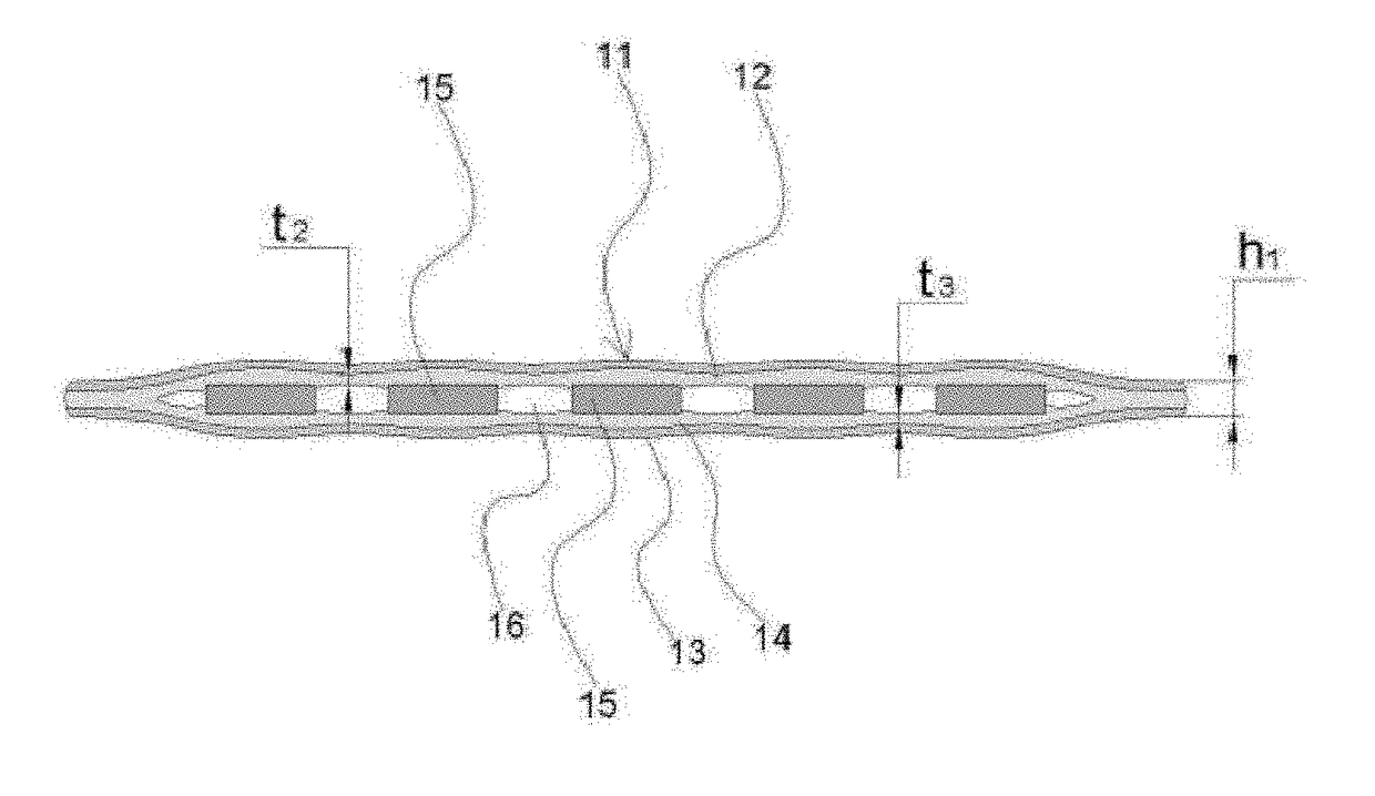
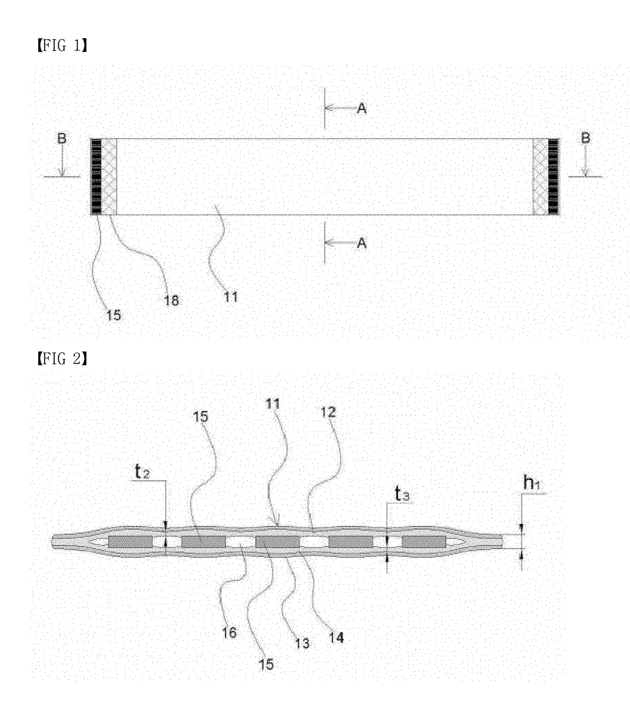
[0073]First, referring to FIG. 1 and FIG. 2, a flexible flat cable according to the present invention includes a plurality of conductive wires 15 disposed between an upper film 11 and a lower film 13, wherein the conductive wires 15 are fixed by a first thermal bonding resin 12 of the upper film 11 and a second thermal bonding resin 14 of the lower film 13, an air gap 16 is formed between the conductive wires 15, and a side end of the upper film 11 and a side end of the lower film 13 are bonded by the first thermal bonding resin 12 and the second thermal bonding resin 14.

second embodiment

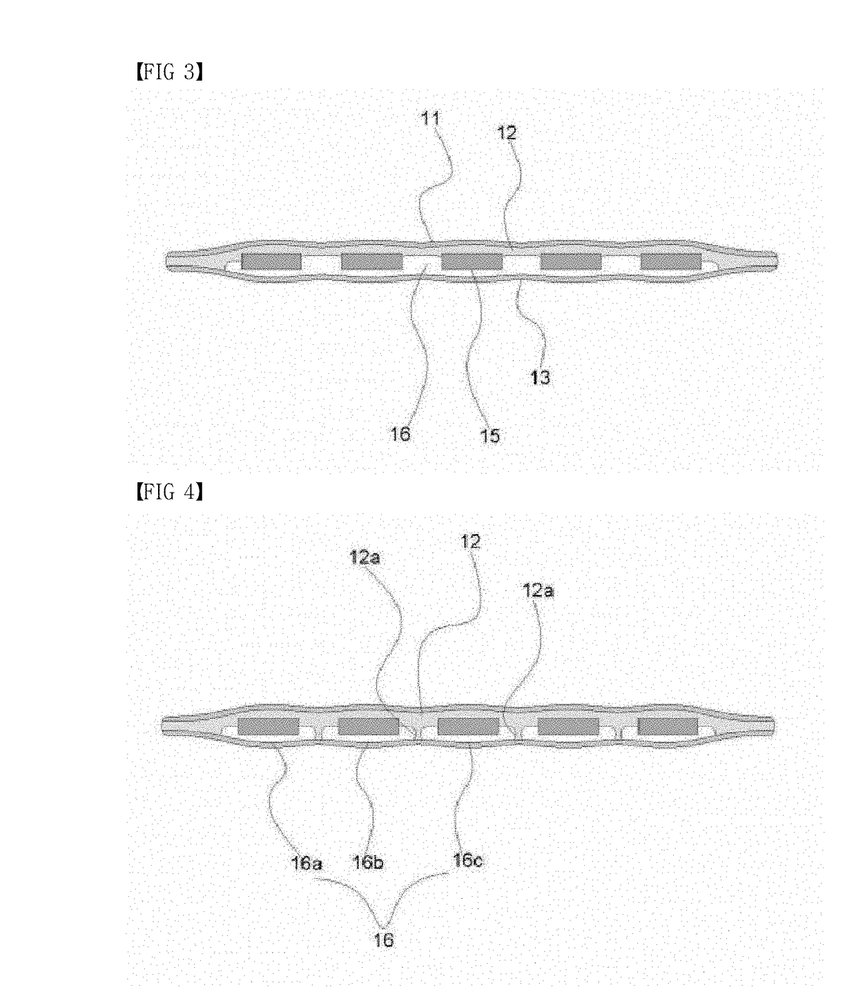
[0074]Referring to FIG. 1 and FIG. 3, a flexible flat cable according to the present invention includes a plurality of conductive wires 15 disposed between an upper film 11 and a lower film 13, wherein the conductive wires 15 are fixed by a first thermal bonding resin 12 applied to a lower surface of the upper film 11, an air gap 16 is formed between the conductive wires 15 and between the lower film 13 and the conductive wire 15, and a side end of the upper film 11 and a side end of the lower film 13 are bonded by the first thermal bonding resin 12.

[0075]Referring to FIG. 4, the air gap 16 may be divided into a plurality of air gaps 16a, 16b, 16c, . . . by a plurality of partition portions 12a formed at the first thermal bonding resin 12 and arranged between the conductive wires 15.

third embodiment

[0076]Referring to FIG. 1 and FIG. 5, a flexible flat cable according to the present invention includes a plurality of conductive wires 15 disposed between an upper film 11 and a lower film 13, wherein the conductive wires 15 are fixed by a second thermal bonding resin 14 applied to the lower film 13, an air gap 16 is formed between the conductive wires 15 and between the upper film 11 and the conductive wire 15, and a side end of the upper film 11 and a side end of the lower film 13 are bonded by the second thermal bonding resin 14.

[0077]Referring to FIG. 6, the air gap 16 may be divided into a plurality of air gaps 16a′, 16b′, 16c′, . . . by a plurality of partition portions 14a formed at the second thermal bonding resin 14 and arranged between the conductive wires 15.

[0078]Referring to FIG. 7, the air gap 16 may be formed between signal transmission lines 15a and 15b for transmitting signals, and a thermal bonding resin may be filled between the signal transmission line 15a or 15...


PUM


Abstract

The present invention relates to a flexible flat cable including a plurality of conductive wires disposed between an upper film and a lower film, wherein an air gap is formed between the conductive wires. The flexible flat cable according to the present invention includes a plurality of conductive wires (15) disposed between an upper film (11) and a lower film (13), wherein the conductive wires (15) are fixed by a first thermal bonding resin (12) of the upper film (11) and a second thermal bonding resin (14) of the lower film (13), an air gap (16) is formed between the conductive wires (15), and a side end of the upper film (11) and a side end of the lower film (13) are bonded by the first thermal bonding resin (12) and the second thermal bonding resin (14).

Description

BACKGROUND OF THE INVENTION1. Field of the Invention[0001]The present invention relates to a flexible flat cable, and more particularly, to a flexible flat cable in which a plurality of conductive wires are disposed between an upper film and a lower film, and an air gap is formed between the conductive wires.2. Description of the Related Art[0002]“Flat cable covering and flat cable using same” is disclosed in Korean Patent No. 10-0841000 (registered on Jun. 18, 2008).[0003]Referring to the flat cable covering and the flat cable using the same, the flat cable covering is prepared by sequentially laminating on one surface of a heat-resistant substrate film with an adhesivity-improving layer and a flame-retardant heat-adhesive resin layer including 20 wt % to 40 wt % of a heat-adhesive resin mainly including a linear saturated polyester-based resin and 80 wt % to 60 wt % of filler constituents mainly including a mixed flame retardant including at least a hydrated metallic compound, ant...

Claims


Application Information

Patent Timeline
IPC IPC(8): H01B7/08H03H7/38H01B7/04
CPCH01B7/0838H03H7/38H01B7/04H01B7/0823H01B7/2825H01B7/295
Inventor YOON, SANG BO
Owner YOON HEE JUN
Features
  • Generate Ideas
  • Intellectual Property
  • Life Sciences
  • Materials
  • Tech Scout
  • Unparalleled Data Quality
  • Higher Quality Content
  • 60% Fewer Hallucinations
Learn More