User-actuated dynamic tension traction apparatus

a dynamic tension traction and user-actuated technology, applied in the field of medical traction devices, can solve the problems of complex, cumbersome, difficult to carry, etc., and achieve the effect of reducing the number of users

Active Publication Date: 2018-02-01
INNOVATIO DEVICES LLC
View PDF2 Cites 6 Cited by
  • Summary
  • Abstract
  • Description
  • Claims
  • Application Information

AI Technical Summary

Benefits of technology

[0015]Another object of the present disclosure is to provide a traction device for spinal decompression therapy that enables variable direction and variable change in tension pressure in the traction vector.

Problems solved by technology

Most of such devices, however, are complex, cumbersome, not readily portable, or require trained healthcare personnel to place the device on the patient and administer treatment.
However, all prior art devices apply functionally equivalent biomechanical force to the user's spine.
); however, these solutions still apply traction force to the user in a linear direction.
These prior art solutions fail to provide the optimal biomechanical traction force to the user for spinal decompression therapy.
In addition, the linear direction of the force does not provide the optimal resistance to relax and lengthen the patients muscles in his or her or her natural range of motion.

Method used


Image

  • User-actuated dynamic tension traction apparatus
  • User-actuated dynamic tension traction apparatus
  • User-actuated dynamic tension traction apparatus

Examples


Embodiment Construction

[0032]Exemplary embodiments are described herein to provide a detailed description of the present disclosure. Variations of these embodiments will be apparent to those of skill in the art. Moreover, certain terminology is used in the following description for convenience only and is not limiting. For example, the words “right,”“left,”“top,”“bottom,”“upper,”“lower,”“inner” and “outer” designate directions in the drawings to which reference is made. The word “a” is defined to mean “at least one.” The terminology includes the words above specifically mentioned, derivatives thereof, and words of similar import.

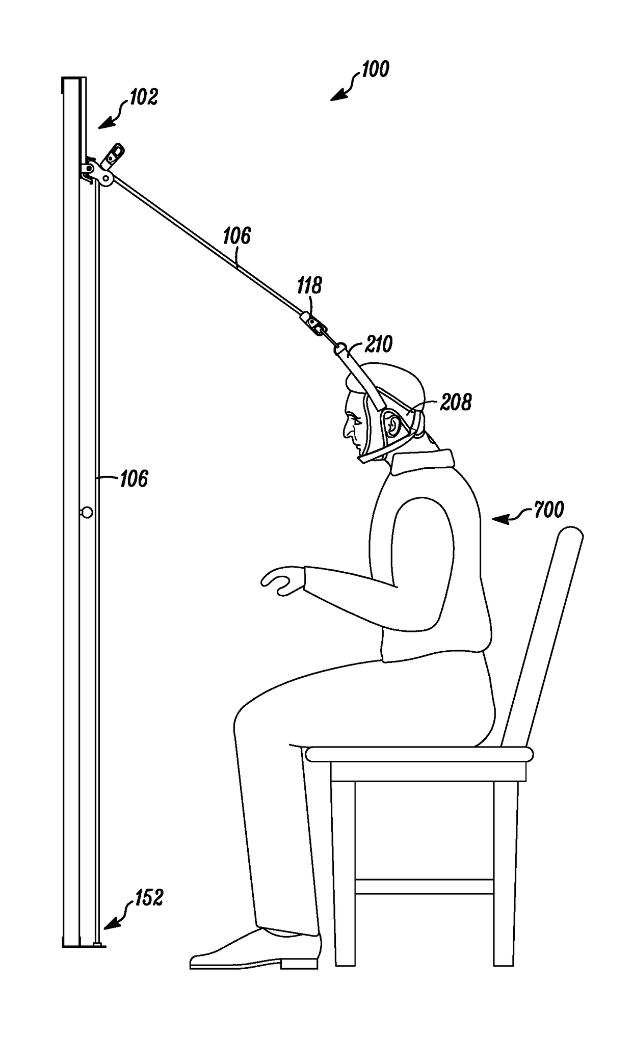
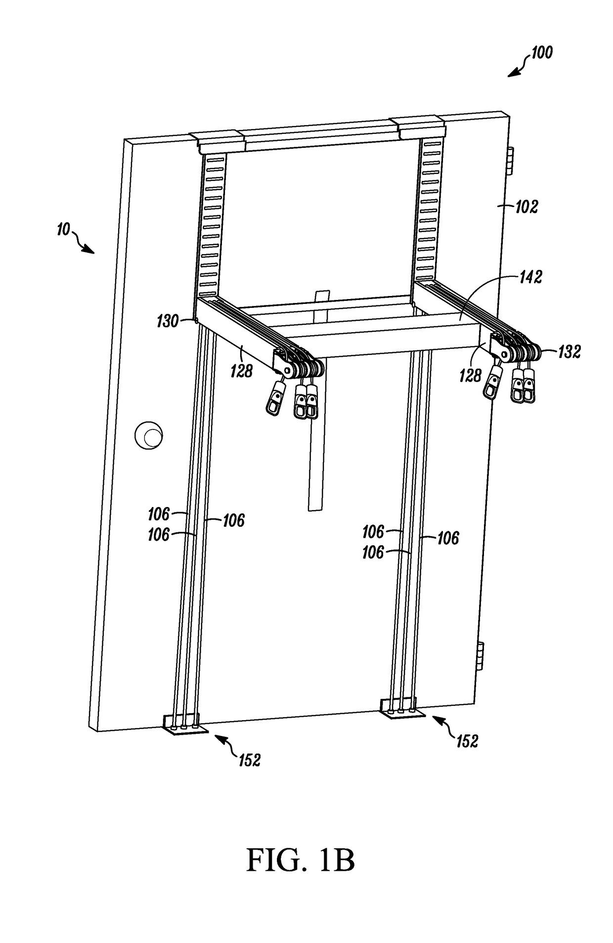
[0033]Embodiments of the present disclosure provide for a dynamic tension traction apparatus for spinal decompression therapy. Embodiments of the present disclosure solve problems associated with prior art traction devices that apply traction force using static deadweight, and prior art traction devices that apply traction in a single force vector. Prior art traction devices apply...


PUM


Abstract

A user-actuated dynamic tension traction device is disclosed. According to various embodiments of the present disclosure, a traction device passively applies traction force to a user through the use of one or more rubber or elastic resistance bands coupled to a neck collar worn by the user. The resistance bands are anchored to a stationary surface (in a preferred embodiment a door). Traction is passively applied to the user, rather than actively, as the user moves his or her body away from the surface to which the resistance bands are anchored. As the user moves backward and stretches the resistance bands, tension is incrementally exerted by the resistance bands on the neck collar, and traction is gradually applied to the user's spine.

Description

FIELD[0001]The present disclosure relates to the field of medical traction devices; in particular, to portable spinal decompression devices.BACKGROUND[0002]Spinal decompression therapy is a non-surgical, non-invasive treatment for certain types of chronic back pain that works by slowly and gently stretching the spine, taking pressure off compressed discs and vertebrae. A myriad of devices has been developed for providing decompression or applying traction to the human spine. Specifically, these devices are used to treat disc bulges, disc herniations, facet syndrome, nerve impingement, spinal / foraminal stenosis, degenerative disc disease, osteoarthritis in the spine, muscle spasm, tension headaches, decreased joint space, decreased range of motion and facet joint inflammation. Typically, the apparatus includes some type of sling or harness to cradle the head with pressure applied thereto by means of pulleys and weights, often involving fixtures to a bed or wall. Commonly, assistance ...

Claims


Application Information

Patent Timeline
Patent Type & Authority Applications(United States)
IPC IPC(8): A61H1/02
CPCA61H1/0292A61H1/0296A61H2203/0425A61H2201/1659A61H2201/1611A61H2001/0207A61H2201/1607A61H2203/0493A61H2201/1673A61H1/0229
Inventor ADIMARI, ANTONIO
Owner INNOVATIO DEVICES LLC
Why Eureka
Try Eureka