Hermetic refrigerant compressor and refrigeration apparatus
a refrigerant compressor and compressor technology, applied in the direction of magnetic circuit rotating parts, piston pumps, magnetic circuit shapes/forms/construction, etc., can solve the problems of vibration of the refrigerant compressor, unbalanced load in the lateral direction, and unbalanced load, so as to achieve a small size and reduce vibration
- Summary
- Abstract
- Description
- Claims
- Application Information
AI Technical Summary
Benefits of technology
Problems solved by technology
Method used
Image

Examples
embodiment 1
[0033][Configuration of Sealed Refrigerant Compressor]
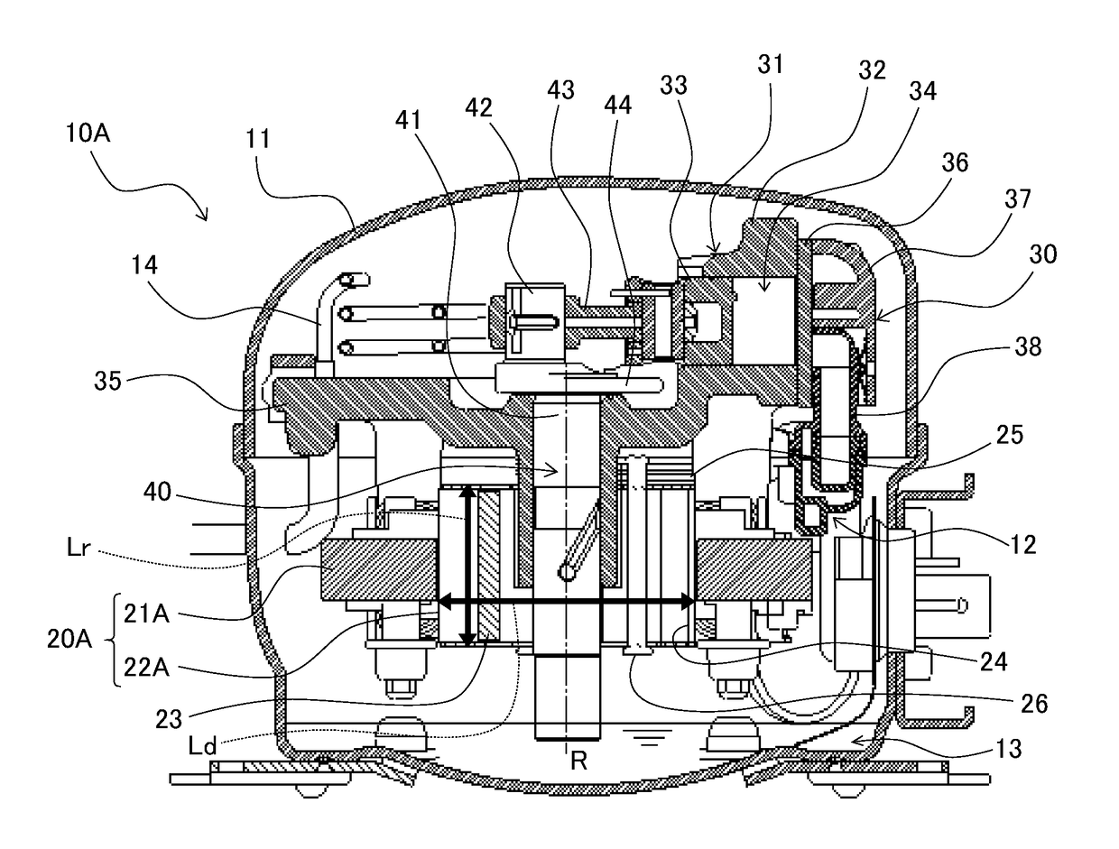
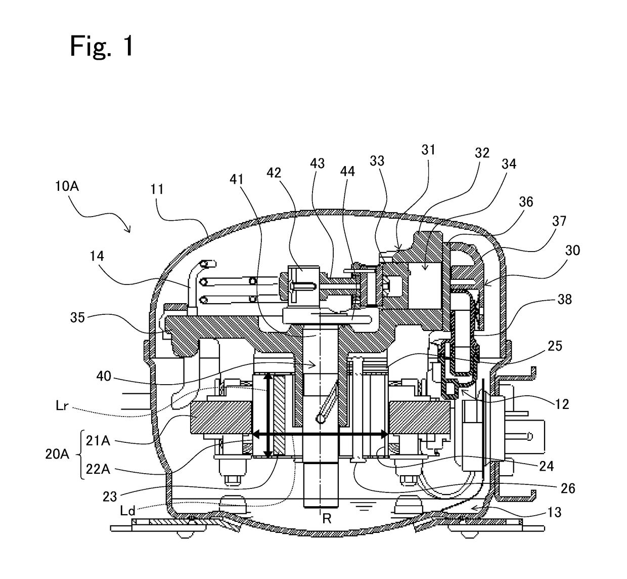
[0034]Referring to FIG. 1, a sealed refrigerant compressor 10A according to Embodiment 1 includes an electric component 20A and a compression component 30 which are accommodated in a sealed container 11, and a refrigerant gas and lubricating oil 13 are reserved in the sealed container 11. The electric component 20A and the compression component 30 constitute a compressor body 12. The compressor body 12 is disposed inside the sealed container 11 in a state in which the compressor body 12 is elastically supported by a suspension spring (not shown) provided on the bottom portion of the sealed container 11.
[0035]The sealed container 11 is provided with a suction pipe (not shown) and a discharge pipe (not shown). The first end of the suction pipe is in communication with the inner space of the sealed container 11, and the second end thereof is connected to a refrigeration device (not shown), thus constituting a refrigeration cycle suc...
modified example
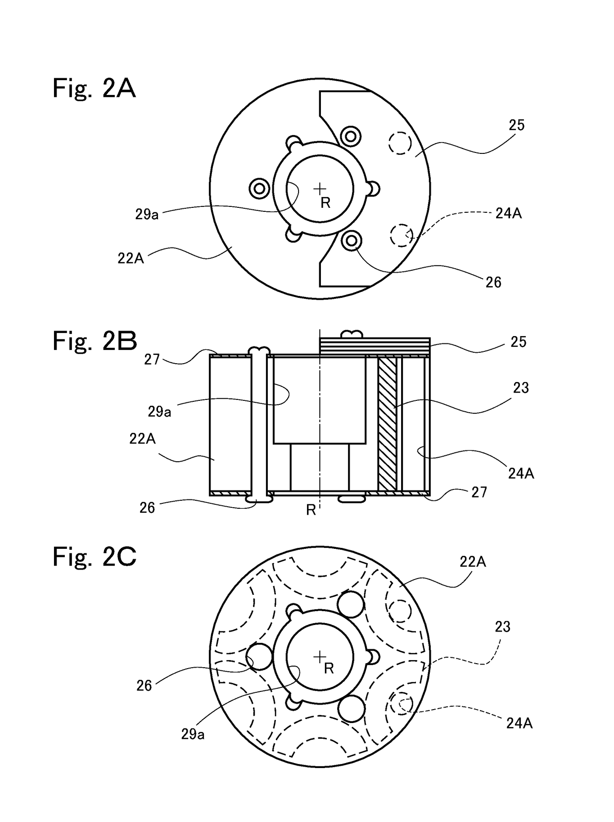
[0079]In the present embodiment, as shown in FIGS. 1 and 2B, the balance holes are configured as the through-holes (balance through-holes 24A) extending in the direction of the rotational axis R of the rotor 22A. This configuration is merely exemplary. For example, the balance holes may not be the through-holes, and may be, for example, balance blind holes 24C, 24D (blind holes having bottoms) of FIGS. 3A and 3B. In a case where the balance holes are the blind holes, the blind holes may be provided only in the upper surface of the rotor 22A as shown in FIG. 3A, may be provided only in the lower surface of the rotor 22A, or may be provided in both of the upper and lower surfaces of the rotor 22A.
[0080]In a case where the balance holes are the blind holes, the depths of the balance holes are not particularly limited. The depths of the plurality of blind holes may be equal to each other or different from each other. At this time, for example, as shown in FIG. 3B, it is preferable that ...
embodiment 2
[0088]The above-described sealed refrigerant compressor 10A of Embodiment 1 includes the electric component 20A which is the inner rotor motor. This is merely exemplary. An electric component may be an outer rotor motor. Specifically, as shown in FIG. 5, a sealed refrigerant compressor 10B according to Embodiment 2 includes an electric component 20B and the compression component 30 (compressor body 12) which are accommodated in the sealed container 11, and the refrigerant gas and the lubricating oil 13 are reserved in the sealed container 11, as in the sealed refrigerant compressor 10A according to Embodiment 1. The electric component 20B is the outer rotor motor.
[0089]The electric component 20B includes at least a stator 21B and a rotor 22B, as in the electric component 20A according to Embodiment 1. As can be seen from the plan view of FIG. 6A or the longitudinal sectional view of FIG. 6B, the stator 21B has a stator shaft hole 29c in a center portion thereof. The bearing unit 35 ...
PUM
 Abstract
Description
Claims
Application Information
 - R&D Engineer
- R&D Manager
- IP Professional
- Industry Leading Data Capabilities
- Powerful AI technology
- Patent DNA Extraction
Browse by: Latest US Patents, China's latest patents, Technical Efficacy Thesaurus, Application Domain, Technology Topic.
© 2024 PatSnap. All rights reserved.Legal|Privacy policy|Modern Slavery Act Transparency Statement|Sitemap