
Refrigerator

a technology for refrigerators and freezers, applied in the field of refrigerators, can solve the problems of user needs, affecting the operation of the refrigerator body, and the components mounted on the rear surface of the refrigerator door may interfere with each other, so as to achieve smooth operation, stable maintenance, and reduce the burden on the withdrawal unit

Active Publication Date: 2018-02-08
LG ELECTRONICS INC
View PDF16 Cites 24 Cited by
  • Summary
  • Abstract
  • Description
  • Claims
  • Application Information

AI Technical Summary

Benefits of technology

The invention is a drawer system that reduces the load burden on the withdrawal unit and allows for smooth operation. It also ensures stable maintenance of the drawer without wobbling during the withdrawal of the drawer. The rear frame structure facilitates the circulation of chilly air and increases the food storage capacity. The rear frame acts as a pushing force to the drawer only by contacting it while moving in a forward direction, and a return unit automatically returns the drawer to the original location. The user can select whether or not to use the automatic withdrawal function.

Problems solved by technology

In this case, when a refrigerator door is closed, shelves or drawers mounted in the storage compartment of the refrigerator body and components mounted on the rear surface of the refrigerator door may interfere with each other.
Accordingly, there is inconvenience in that a user needs to dip into the storage compartment to withdraw food and drink stored in the drawer, and it is difficult for a user to check foods stored at the rear side of the storage compartment.
These limitations are further intensified as the storage compartment deepens in accordance with the trend of enlargement of the refrigerator.
Accordingly, it is important to design the structure of the storage frame so as to sufficiently bear the loads, and thus the structure of the storage frame becomes complicated, and the volume there of increases.
Accordingly, the weight of the storage frame itself becomes heavier, and the space occupied by the storage frame increases, thereby causing a reduction of the capacity of storage compartment.
Thus, the line of action of a force by the link and the line of action of an inertial force by the drawer do not exist on the same line, causing a bending moment or a shearing force to act on the storage frame and thus causing a deformation, which is intensified as the weight of stored foods in the drawer increases.
In this case, there are many practical limitations in designing the rail that can sufficiently bear the load acting from the storage frame in a determined standard.
Also, in a structure in which all loads applied from the storage frame are concentrated on the rail, the storage frame may easily wobble during the movement.
When this wobbling lasts and thus the rail or the storage frame is deformed, the movement operation of the storage frame cannot be stably performed.
Also, since the arm needs to be installed to correspond to the height of the shelf, the installation location of the arm is limited.
Particularly, most part of the arm connected to the shelf located in the middle of the storage compartment is inevitably exposed to a user.
Thus, the exterior is not good, and the storage space decreases by a space occupied by the storage frame.
In addition, the circulation of chilly air in the storage compartment is interrupted by the storage frame.
Also, although a user does not desire a function of automatically withdrawing the drawer, he / she cannot select whether or not to use the automatic withdrawal function.
Accordingly, when a user opens the door that is closed, a force for separating the gasket from the cabinet and a force for withdrawing the storage frame are simultaneously needed, making it difficult to open the door.

Method used


Image

  • Refrigerator
  • Refrigerator
  • Refrigerator

Examples


Embodiment Construction

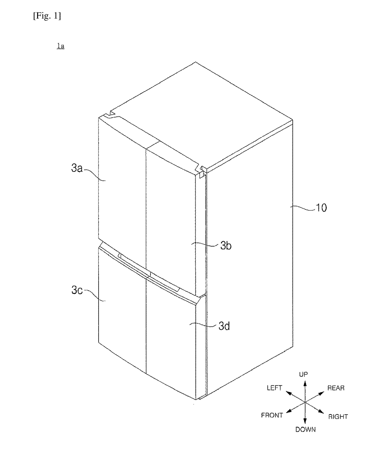
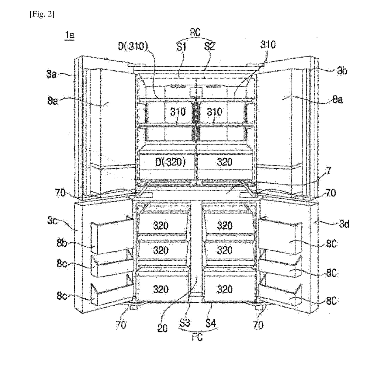
[0083]FIG. 1 is illustrates an example refrigerator 1a. FIG. 2 is illustrates an example refrigerator 1a with doors 3a, 3b, 3c and 3d opened. FIG. 3 illustrates an example storage compartment S3 of a refrigerator 1a. The expressions denoting directions such as “front / forward,”“rear / backward,”“left,”“right,”“up,” and “down” mentioned below will be defined as indicated in FIG. 1.

[0084]Referring to FIGS. 1 and 2, the refrigerator 1a may include a cabinet 10 including compartments RC and FC (or, storage compartment S1, S2, S3 and S4) formed therein, and doors 3a, 3b, 3c and 3d for opening and closing the compartments RC and FC. The doors 3a, 3b, 3c and 3d may be pivotably connected to the cabinet 10.

[0085]The compartments RC and FC may have a front face opened so as to receive foods therethrough, and the opened front face of the compartments RC and FC may be opened and closed by the doors 3a, 3b, 3c and 3d. Chilly air may be supplied into the compartments RC and FC, and the compartments...


PUM


Abstract

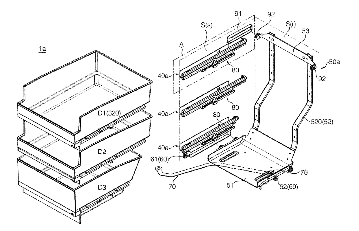
A refrigerator includes a cabinet that includes a storage compartment. The refrigerator further includes a door. The refrigerator further includes a drawer. The refrigerator further includes a drawer guide that is configured to support the drawer and that is configured to guide the drawer based on the drawer moving forward and backward. The refrigerator further includes a withdrawal unit that is configured to push the drawer forward based on the door opening. The withdrawal unit includes a base part that is located under the drawer, that is configured to move forward based on the door opening, and that is configured to move backward based on the door closing. The withdrawal unit further includes a rear frame that extends from the base part to a rear side of the drawer and that is configured to push the drawer forward based on the base part moving forward.

Description

TECHNICAL FIELD[0001]The present disclosure relates to a refrigerator.BACKGROUND ART[0002]Generally, refrigerators are home appliances configured to contain food and drink at lower temperatures inside storage spaces shielded by doors. A refrigerator is configured to contain stored foods and drinks in top shape by cooling the inside of a storage space by using cold air generated through heat exchange with a refrigerant circulating a refrigeration cycle. Recently, the refrigerator is increasing in size, and devices such as home bar, ice maker, shelf, or door box are being installed onto rear surface of the refrigerator door. In this case, when a refrigerator door is closed, shelves or drawers mounted in the storage compartment of the refrigerator body and components mounted on the rear surface of the refrigerator door may interfere with each other.[0003]In order to overcome this interference limitation, the front end portions of the drawers (e.g., shelves or drawers) mounted in the st...

Claims


Application Information

Patent Timeline
Patent Type & Authority Applications(United States)
IPC IPC(8): F25D25/02F25D23/02
CPCF25D25/025F25D23/028F25D23/067A47B2210/175
Inventor YANG, CHANGWOANCHOI, SEUNGJINKIM, HANHYOPARK, YOOMINPARK, MINWOOHAN, TACKWON
Owner LG ELECTRONICS INC
Learn More