Vehicle detection apparatus

a detection apparatus and vehicle technology, applied in the field of vehicles, can solve the problems of reduced accuracy of sensors, high installation cost, and easy damage, and achieve the effect of accurately detecting and distinguishing vehicles, accurate determination of the lateral position of vehicles, and minimal inductive effect of vehicles passing in adjacent lan

Active Publication Date: 2018-02-08
RED FOX I D LTD
View PDF21 Cites 1 Cited by
  • Summary
  • Abstract
  • Description
  • Claims
  • Application Information

AI Technical Summary

Benefits of technology

[0011]The arrangement of inductive loops according to the invention allows for accurate determination of the lateral position of a vehicle as it passes over the loops. By evaluating the signals from the loops in combination, a single vehicle straddling two lanes, or two vehicles (e.g. motorcycles) travelling in a single lane can be accurately detected and distinguished.
[0012]Each pair of loops substantially extends across the full width of each lane. Of course, in practice there will be a small gap between loops in adjacent lanes, but the size of the lateral gap is much smaller than in existing systems, typically less than around 30 cm (1 foot). A lateral gap of this size is sufficiently small to ensure detection of motorcycles riding between lanes, but sufficiently large to ensure that inductive coupling between loops does not cause excessive noise or loop controller malfunction, and to ensure that the inductive effect of a vehicle passing in an adjacent lane is minimal.

Problems solved by technology

However, these types of sensors suffer from reduced accuracy whenever there is rain, mist or snow.
They can be expensive to install, and their overhead location makes them vulnerable to damage by electrical storms and sometimes vandalism.
Inductive loops are generally cheaper to install, more reliable and less vulnerable to damage as compared with overhead sensors, but suffer from a lack of accuracy in certain road conditions.
For example, in an area where vehicles often change lanes, vehicles can be mis-counted if they are straddling two lanes when passing over the loops.
This is because it can be difficult to determine whether inductive disturbances occurring in loops in two adjacent lanes result from passage of two vehicles in adjacent lanes, or from a single vehicle straddling the two lanes.
Motorcycles are also prone to mis-counting, since they often drive between lanes, and sometimes two motorcycles ride side-by-side in a single lane.
This system works well for traffic which has good lane discipline, but accuracy suffers in situations where many vehicles are changing lanes over the measurement site, or where the vehicle mix includes more than a small proportion of motorcycles.
It is sometimes possible to distinguish one straddling vehicle from two in-lane vehicles by evaluating the geometric mean of the peak change in inductance in loops in adjacent lanes, and testing the geometric mean against a threshold, but the accuracy of this method leaves room for improvement, and motorcycles are often missed altogether.

Method used


Image

  • Vehicle detection apparatus
  • Vehicle detection apparatus
  • Vehicle detection apparatus

Examples


Embodiment Construction

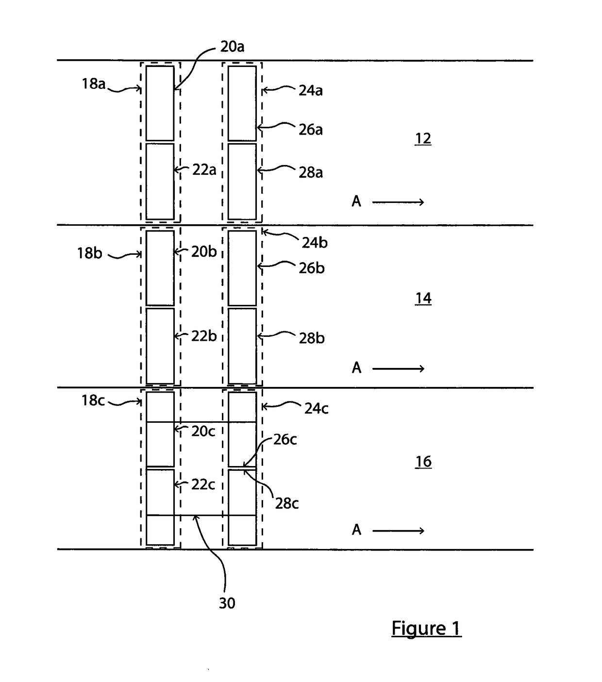
[0030]Referring firstly to FIG. 1, a three-lane carriageway is shown. Each lane 12, 14, 16 is for vehicles travelling in the same direction. The direction of travel is indicated by arrows A. In the following description, references to “length” or “along” the lane refer to the direction indicated by arrows A, and references to “width” or “across” the lane refer to a direction substantially perpendicular to arrows A.

[0031]A first pair of loops 18a, 18b, 18c is provided respectively across each of the three lanes 12, 14, 16. Each loop pair 18a, 18b, 18c extends substantially across the full width of its respective lane. The loop pair 18a includes two loops 20a, 22a, and likewise the loop pair 18b has two loops 20b, 22c, and the loop pair 18c has two loops 20c, 22c. Each loop 20abc, 22abc is substantially rectangular, having a length along its respective lane 12, 14, 16 and a width across the lane 12, 14, 16. The width of each loop 20abc, 22abc is substantially half of the width of its ...


PUM


Abstract

Apparatus is disclosed for monitoring use of a carriageway, the carriageway having two or more lanes (12, 14, 16) for use by vehicles travelling in a single direction A, the apparatus including: a pair of inductive loops (20abc, 22abc) on or in the surface of each lane (12, 14, 16), the loops in the pair being positioned substantially side-by-side across the lane (12, 14, 16) and the pairs of loops (18a, 18b, 18c) being positioned substantially side-by-side across the carriageway, each pair of loops (18abc) substantially extending across the full width of the lane (12, 14, 16), and each loop having a length in the direction of vehicle travel which is substantially shorter than the width of the loop across the lane; a loop controller associated with each loop, each loop controller energising its associated loop and carrying out measurements of the inductance of its associated loop; and processing means for receiving the measurements from the loop controllers, and for using the measurements for calculating the estimated position of vehicle(s) on the carriageway.

Description

[0001]The present invention relates to apparatus for detecting and counting vehicles travelling along a carriageway, in particular to apparatus including inductive loops on or in the road surface.BACKGROUND TO THE INVENTION[0002]It is known to use various different types of apparatus to monitor usage of a road, which is done for various purposes, including to identify congested areas and plan future infrastructure.[0003]Currently-used apparatus includes various types of overhead sensors, for example laser sensors or video cameras. However, these types of sensors suffer from reduced accuracy whenever there is rain, mist or snow. They can be expensive to install, and their overhead location makes them vulnerable to damage by electrical storms and sometimes vandalism.[0004]Inductive loops are also known, and can be buried in the road to detect traffic as it passes over the loop. Inductive loops are generally cheaper to install, more reliable and less vulnerable to damage as compared wi...

Claims


Application Information

Patent Timeline
Patent Type & Authority Applications(United States)
IPC IPC(8): G08G1/042
CPCG08G1/042
Inventor LEES, RICHARD ANDREW
Owner RED FOX I D LTD
Why Eureka
Try Eureka