Lubricating device of gear apparatus for vehicle

a technology of lubricating device and gear apparatus, which is applied in the direction of mechanical equipment, gearing details, transportation and packaging, etc., can solve the problems of increasing mechanical loss and increasing agitation loss, and achieve the effect of increasing mechanical loss and ensuring durability

Active Publication Date: 2018-02-15
TOYOTA JIDOSHA KK
View PDF6 Cites 7 Cited by
  • Summary
  • Abstract
  • Description
  • Claims
  • Application Information

AI Technical Summary

Benefits of technology

[0007]Meanwhile, in the lubricating method of lubricating both the low-rotation-side gear and the high-rotation-side gear through the forced lubrication in the lubricating device of the gear apparatus for the vehicle of the above-described related art, it is possible to secure durability of the low-rotation-side gear and the high-rotation-side gear, but for example, there might be caused a problem that a so-called agitation loss becomes greater because the lubricating oil on the tooth surfaces is sandwiched and pressurized at the above meshing position due to a high circumferential speed, or the like; consequently, a mechanical loss becomes greater.

Problems solved by technology

Meanwhile, in the lubricating method of lubricating both the low-rotation-side gear and the high-rotation-side gear through the forced lubrication in the lubricating device of the gear apparatus for the vehicle of the above-described related art, it is possible to secure durability of the low-rotation-side gear and the high-rotation-side gear, but for example, there might be caused a problem that a so-called agitation loss becomes greater because the lubricating oil on the tooth surfaces is sandwiched and pressurized at the above meshing position due to a high circumferential speed, or the like; consequently, a mechanical loss becomes greater.

Method used


Image

  • Lubricating device of gear apparatus for vehicle
  • Lubricating device of gear apparatus for vehicle
  • Lubricating device of gear apparatus for vehicle

Examples


first embodiment

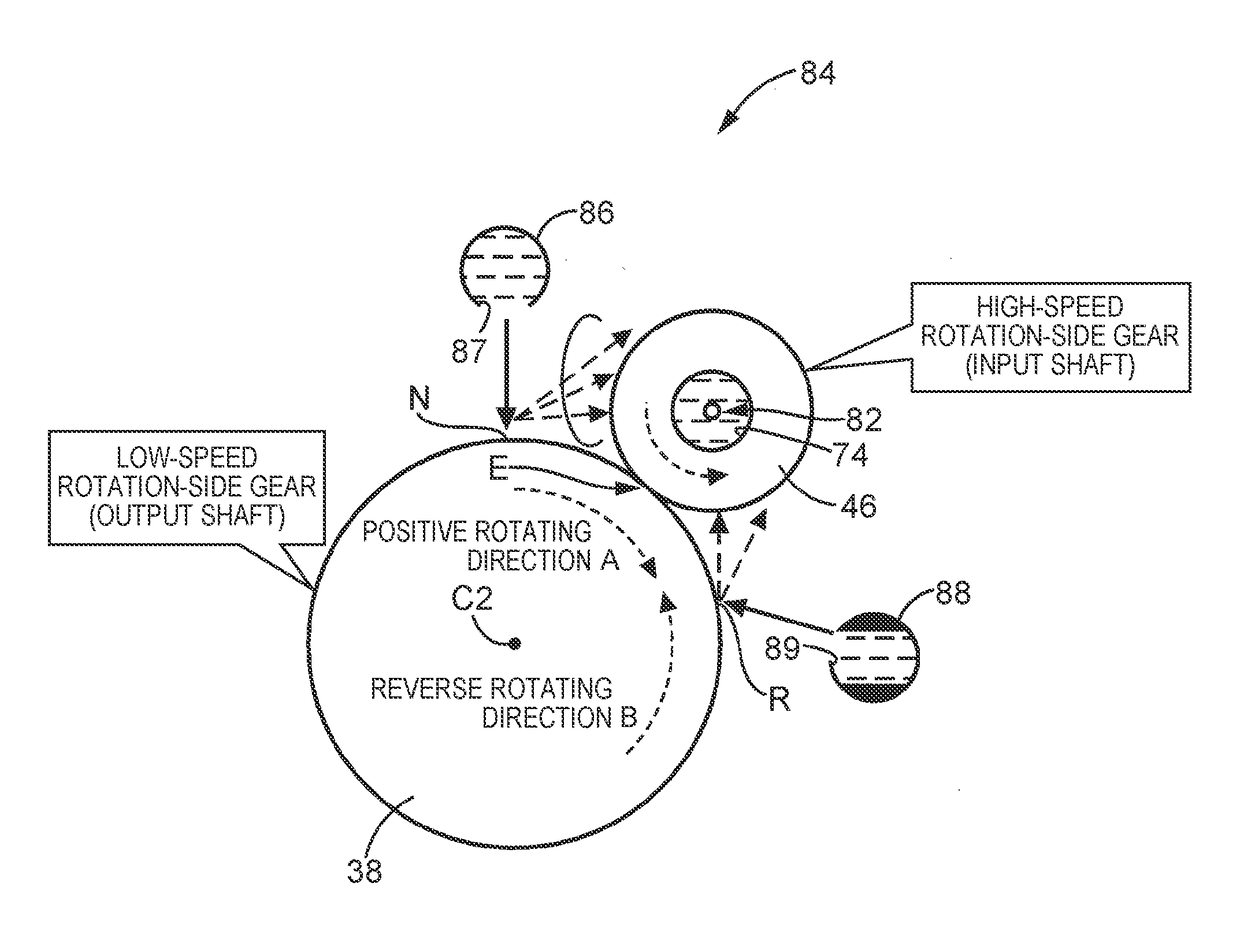
[0047] the lubricating oil is directly supplied to the tooth surface position of the low-rotation-side gear located more upstream of the rotating direction than the meshing position of the low-rotation-side gear with the high-rotation-side gear by the tooth surface lubricating oil supply part, thereby spraying some of the lubricating oil supplied to the tooth surface position toward the tooth surface of the high-rotation-side gear by the rotation of the low-rotation-side gear. Hence, the tooth surface of the high-rotation-side gear is supplied with the lubricating oil not directly but through spraying by the rotation of the low-rotation-side gear; thus, it is possible to secure the durability of the low-rotation-side gear and the high-rotation-side gear, and reduce the agitation loss because the amount of lubricating oil reaching the meshing position between the low-rotation-side gear and the high-rotation-side gear. In addition, because the lubricating oil is supplied into the shaf...

third embodiment

[0049] the tooth surface lubricating oil supply part is arranged such that in the plane orthogonal to the respective rotary axial lines of the low-rotation-side gear and the high-rotation-side gear, the tangential line that is on the addendum circle of the low-rotation-side gear and passes through tooth surface position is set to pass through the high-rotation-side gear. Accordingly, some of the lubricating oil supplied to the tooth surface position located more upstream of the rotating direction than the meshing position of the low-rotation-side gear with the high-rotation-side gear is more efficiently sprayed toward the tooth surface of the high-rotation-side gear by the rotation of the low-rotation-side gear.

[0050]As aforementioned, the present disclosure has been described in detail with reference to the table and the drawings, but the present disclosure may be carried out by further other aspects, and may be variously changed without departing from the scope of the present disc...


PUM


Abstract

A lubricating device of a gear apparatus for a vehicle lubricates a low-rotation-side gear and a high-rotation-side gear meshing with the low-rotation-side gear. The lubricating device comprises a first tooth surface lubricating oil supply part configured to supply a lubricating oil directly to a tooth surface position located more upstream of a rotating direction of the low-rotation-side gear than a meshing position of the low-rotation-side gear with the high-rotation-side gear so as to spray some of the lubricating oil from the tooth surface position toward a tooth surface of the high-rotation-side gear, and an in-shaft lubricating oil supply part configured to supply the lubricating oil into a shaft of the high-rotation-side gear.

Description

INCORPORATION BY REFERENCE[0001]The disclosure of Japanese Patent Application No. 2016-159039 filed on Aug. 12, 2016 including the specification, drawings and abstract is incorporated herein by reference in its entirety.BACKGROUND[0002]1. Technical Field[0003]The technical field relates to a lubricating device of a gear apparatus for a vehicle to lubricate a low-rotation-side gear and a high-rotation-side gear meshing with the low-rotation-side gear.[0004]2. Description of Related Art[0005]There have been known lubricating devices of gear apparatuses for vehicles to lubricate low-rotation-side gears and high-rotation-side gears meshing with the low-rotation-side gears. In such gear apparatuses for the vehicles, in order to secure durability of gear pairs of the low-rotation-side gears and the high-rotation-side gears, it is required to securely perform both formation of oil films on tooth surfaces of the low-rotation-side gears and the high-rotation-side gears and cooling of the too...

Claims


Application Information

Patent Timeline
Patent Type & Authority Applications(United States)
IPC IPC(8): F16H57/04
CPCF16H57/0431F16H57/045F16H57/0456F16H57/042F16H57/043F16H57/0482F16H57/0483B60K6/445F16H57/0457F16H57/046F16H57/0484Y02T10/62
Inventor HORI, TETSUOOKUNO, HAKUBANISHIKAWA, YUKINOBUKIYOKAMI, HIROAKI
Owner TOYOTA JIDOSHA KK
Why Eureka
Try Eureka