Continuously Variable Valve Lift System for Engine

a technology of continuous variable valves and lift systems, which is applied in the direction of valve arrangements, machines/engines, mechanical equipment, etc., can solve the problems of complicated combining structures, high cost, and inability to improve engine power and reduce fuel consumption, so as to improve precision and reliability, simple operation, and easy to ensure durability

Active Publication Date: 2009-12-03
HYUNDAI MOTOR CO LTD
View PDF1 Cites 11 Cited by
  • Summary
  • Abstract
  • Description
  • Claims
  • Application Information

AI Technical Summary

Benefits of technology

[0012]Various aspects of the present invention are directed to provide a continuously variable valve lift system for an engine that has a compact configuration with reduced number or components and disposed under the camshaft in the cylinder head to simply operate with improved precision and reliability and easily secure durability, and particularly, that makes it possible to improve free of layout in the engine compartment by reducing total height of the cylinder head to decrease the size of the engine.

Problems solved by technology

Therefore, because an engine worked under a fixed valve lift and duration, it was impossible to improve the engine power and reduce fuel consumption by changing the valve lift and duration.
However, according to continuously variable valve lift systems in the related art, a lot of components were used and the combining structures were complicated.
Therefore, the entire size of an engine equipped with the continuously variable valve lift system had to be increased, such that the space occupied by the engine in the engine compartment was increased, which made it difficult to set a layout of other devices.
Further, there were a lot of moving components and the operational mechanism was correspondingly complicated, such that it was difficult to precisely and reliably adjust the valve lift and duration and secure sufficient durability for the entire variable mechanism of the engine equipped with the system.

Method used


Image

  • Continuously Variable Valve Lift System for Engine
  • Continuously Variable Valve Lift System for Engine
  • Continuously Variable Valve Lift System for Engine

Examples


Embodiment Construction

[0037]Reference will now be made in detail to various embodiments of the present invention(s), examples of which are illustrated in the accompanying drawings and described below. While the invention(s) will be described in conjunction with exemplary embodiments, it will be understood that present description is not intended to limit the invention(s) to those exemplary embodiments. On the contrary, the invention(s) is / are intended to cover not only the exemplary embodiments, but also various alternatives, modifications, equivalents and other embodiments, which may be included within the spirit and scope of the invention as defined by the appended claims.

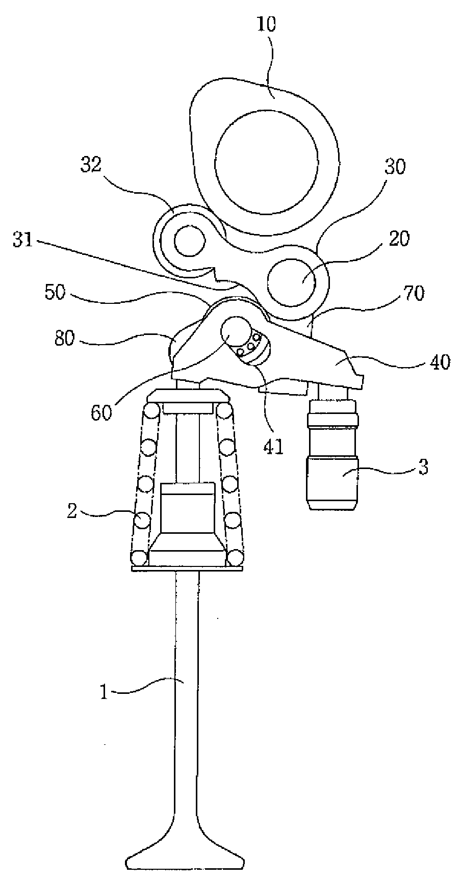
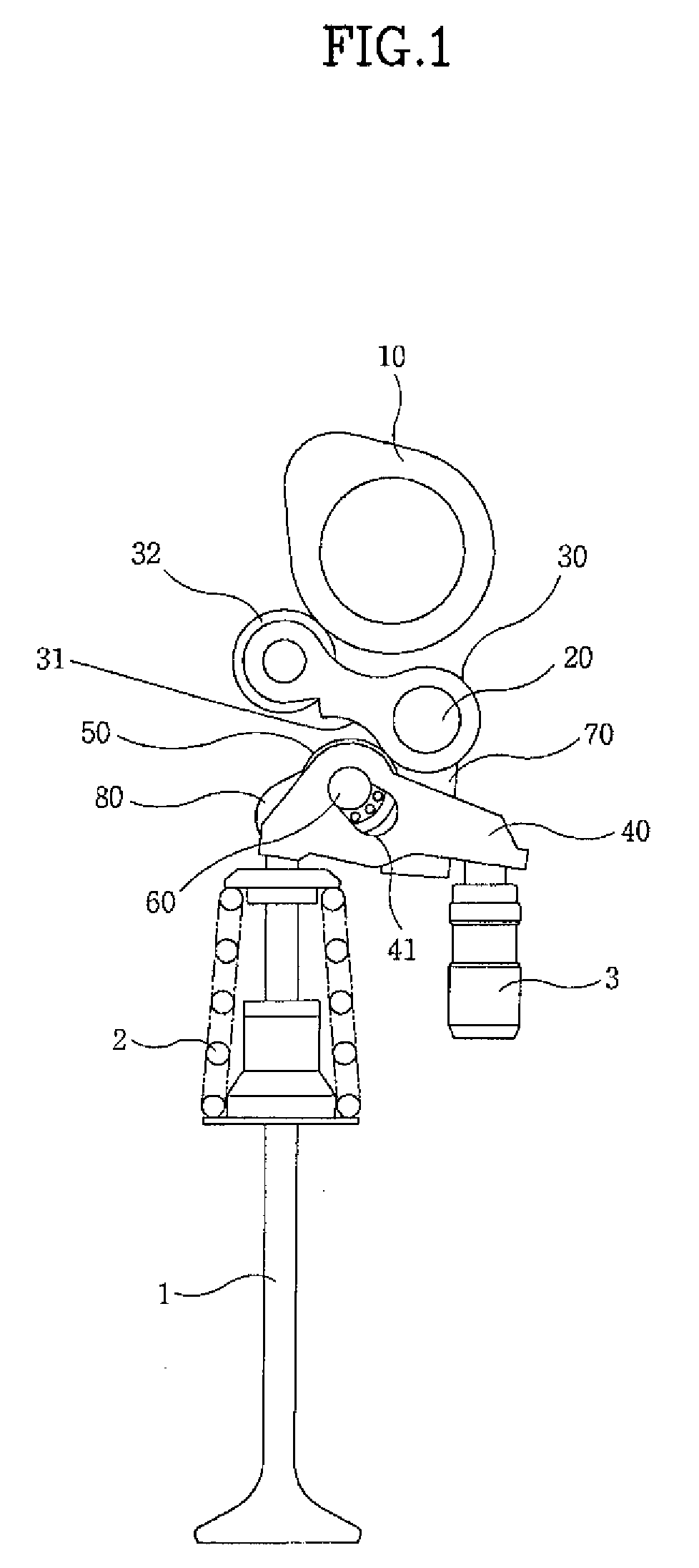
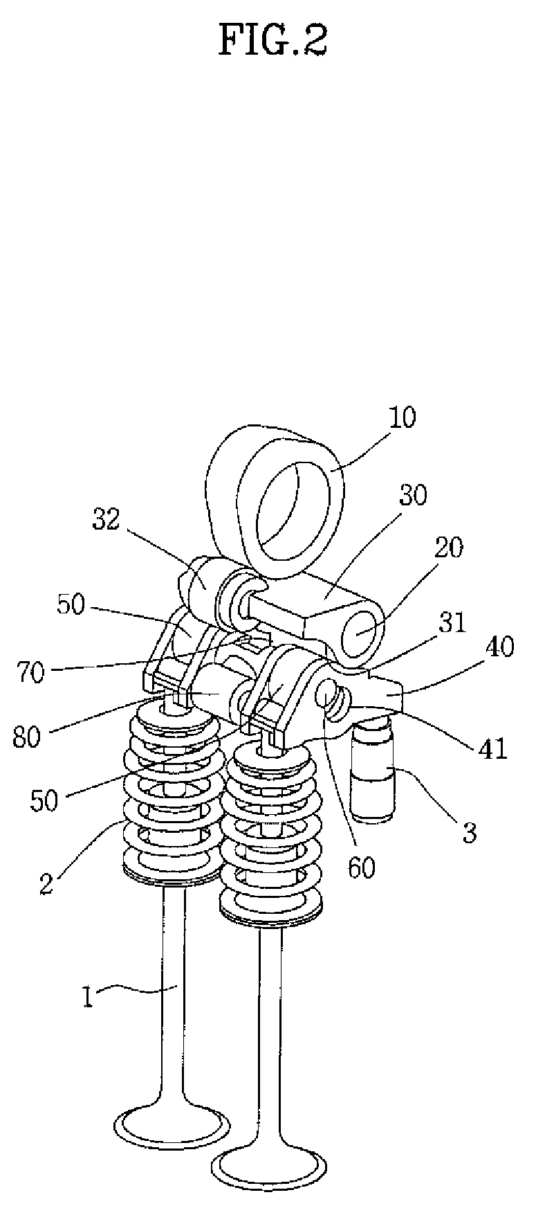
[0038]Referring to FIGS. 1 to 4, a continuously variable valve lift system for an engine includes: a driving cam 10, a control shaft 20, an upper rocker arm 30, lower rocker arms 40, rocker arm followers 50, and a variable mechanism.

[0039]Driving cam 10 is formed on a camshaft that rotates while being connected with a crankshaft throu...


PUM


Abstract

A continuously variable valve lift system for an engine may include a driving cam fixed to a camshaft, a control shaft disposed in parallel to the camshaft with a predetermined distance, an upper rocker arm, one end of which is rotatably coupled to the control shaft and the other end of which is slidably contacted to and rotated by the driving cam, lower rocker arm that is selectively pushed by the upper rocker arm and selectively pushes a valve, rocker arm follower slidably coupled to the lower rocker arm and contacting the upper rocker arm, wherein the rocker arm follower transmits an operational force of the upper rocker arm to the lower rocker arm, and a variable mechanism that changes contact point of the rocker arm follower and the upper rocker arm according to rotation of the control shaft.

Description

CROSS-REFERENCE TO RELATED APPLICATIONS[0001]The present application claims priority to Korean Patent Application Number 10-2008-0050074 filed May 29, 2008, the entire contents of which application is incorporated herein for all purposes by this reference.BACKGROUND OF THE INVENTION[0002]1. Field of the Invention[0003]The present invention relates to a continuously variable valve lift system for an engine, particularly a continuously variable valve lift system for an engine that can adjust opening / closing timings and open / close times of intake / exhaust valves according to rotation of a camshaft.[0004]2. Description of Related Art[0005]According to common actuating mechanism for a valve in the related art, a valve lift was only uniformly formed according to the profile of a driving cam formed on a camshaft, but it was impossible to change the valve lift and duration. Therefore, because an engine worked under a fixed valve lift and duration, it was impossible to improve the engine powe...

Claims


Application Information

Patent Timeline
Patent Type & Authority Applications(United States)
IPC IPC(8): F01L1/34
CPCF01L1/2405F01L13/0063F01L13/0021F01L1/267F01L1/12F01L1/18F01L13/00
Inventor HWANG, YUNSUNG
Owner HYUNDAI MOTOR CO LTD
Why Eureka
Try Eureka