

Hybrid drive device
a drive device and hybrid technology, applied in the direction of mechanical actuators, electric devices, mechanical actuators, etc., can solve the problems of large devices and elaborated to incur a cost increase, difficult control devices, extended time for slip control on second clutches, etc., to prevent a reduction in the durability of friction elements, simple and reliable control, and fast and reliable switching
- Summary
- Abstract
- Description
- Claims
- Application Information
AI Technical Summary
Benefits of technology
Problems solved by technology
Method used
Image

Examples
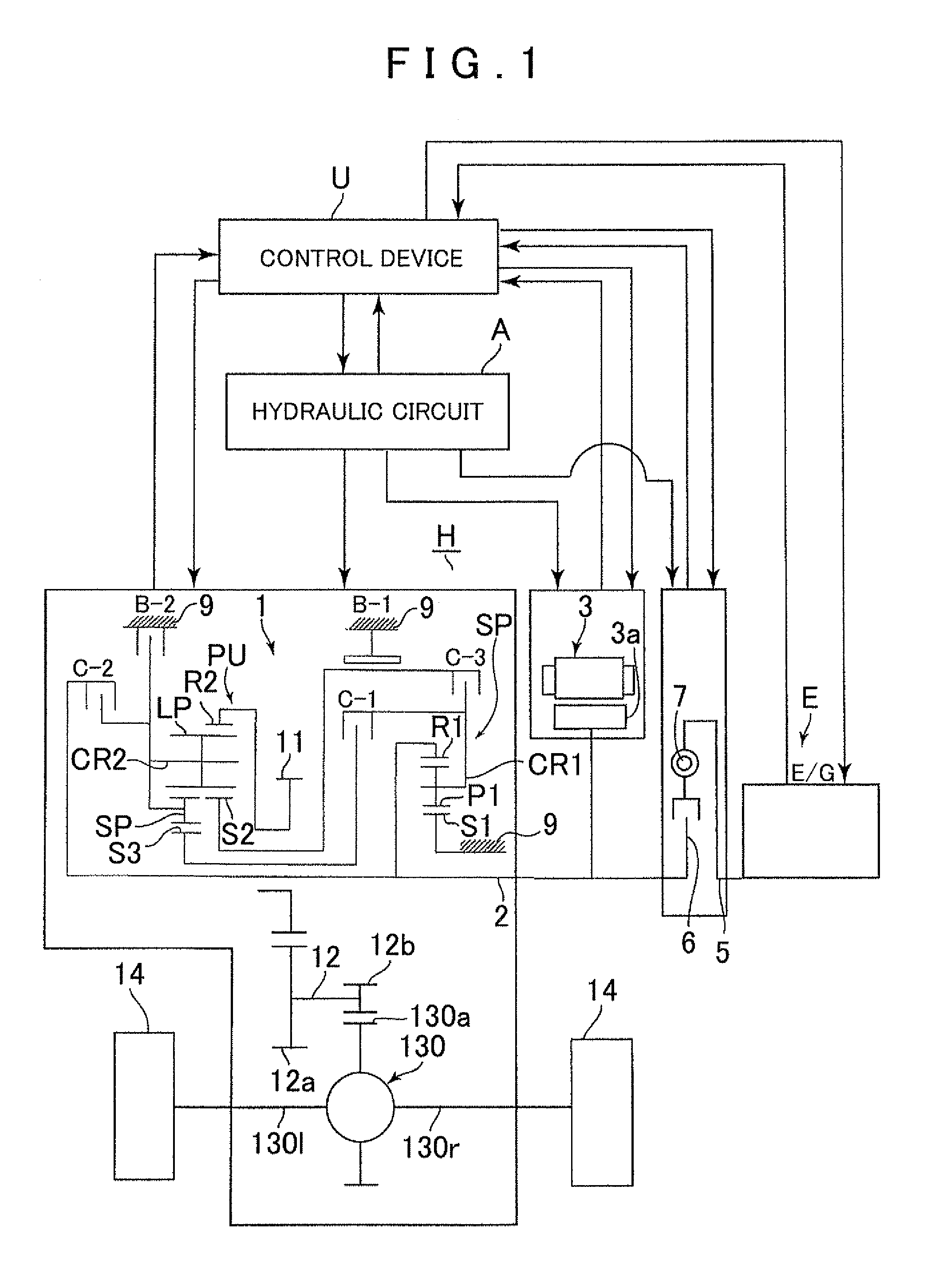
first embodiment
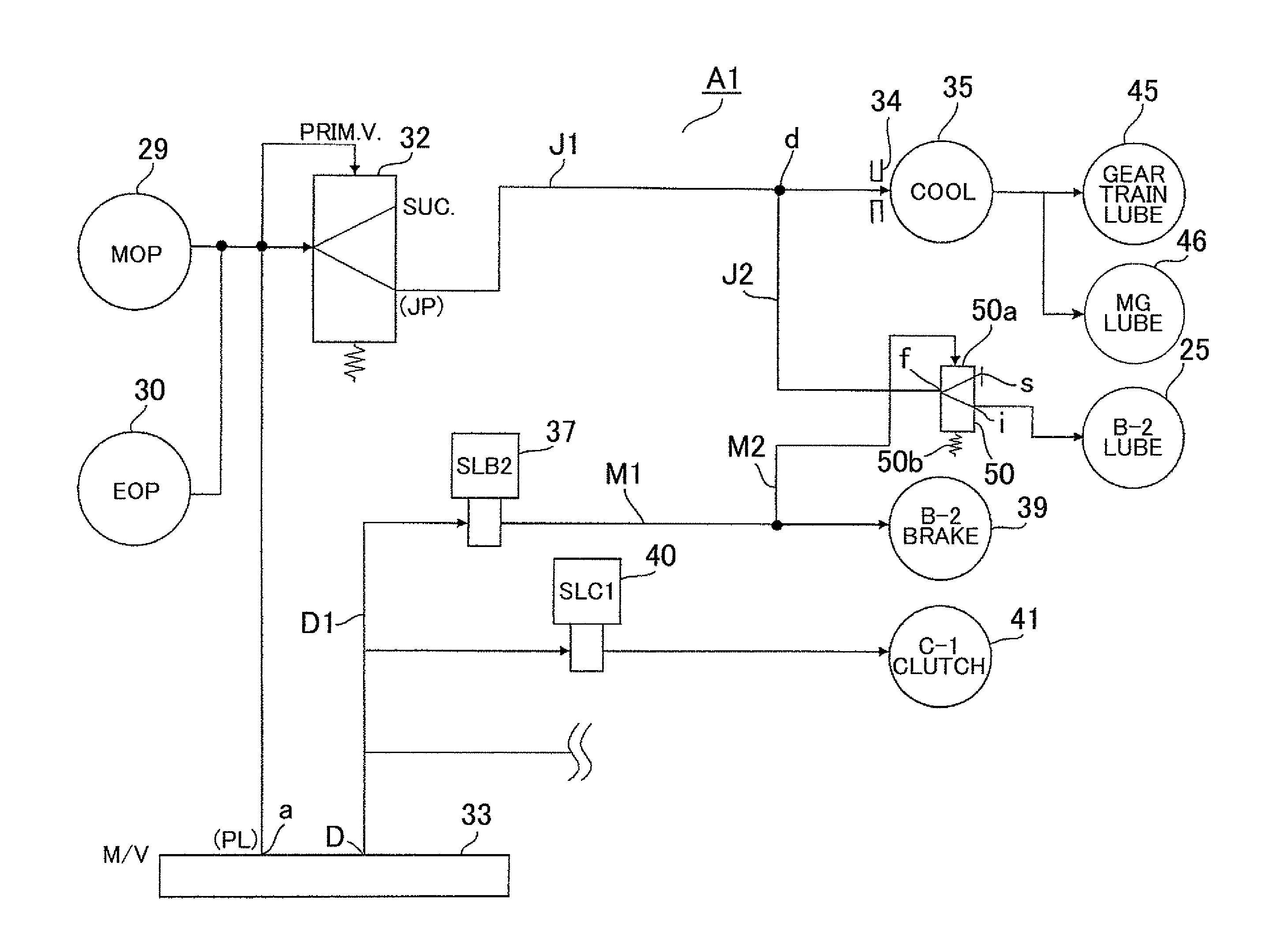
[0037]As shown in FIG. 5, a hydraulic circuit A1 includes a mechanical oil pump 29 and an electric oil pump 30 driven in conjunction with the input shaft 2 of the automatic transmission 1 (or the engine output shaft). The hydraulic pressure generated by these pumps is regulated to a line pressure PL by a primary regulator valve controlled in accordance with an electric signal from the control device (controller) U. Further, a secondary regulator valve 32 that is also controlled in accordance with an electric signal from the controller is disposed on the discharge side of the primary regulator valve to regulate the hydraulic pressure to a lubricating oil pressure JP. The line pressure PL from the primary regulator valve is led to a manual valve 33. The manual valve 33 is switched by an operation for switching between ranges (P, R, N, D, and so forth) performed by a driver. An operation for selecting the D range communicates a line pressure supply port a with a D-range line pressure ...
second embodiment
[0052]In the hydraulic circuit A2 configured as described above, when the vehicle is stationary, the first switching valve 42 connects the lubricating oil passage J on the supply side to the fourth lubricating oil passage J4 so that lubricating oil is supplied to the to-be-lubricated / cooled portion 46 of the electric motor to cool the electric motor 3. When the vehicle is running at a vehicle speed of the predetermined value or more, the first switching valve 42 connects the oil passage J on the supply side to the third lubricating oil passage J3 so that a relatively large amount of lubricating oil pumped by the mechanical oil pump 29 is supplied to the to-be-lubricated portion 45 of the gear trains via the oil cooler 35 to lubricate the gear trains SP and PU, bearings, and so forth of the automatic transmission 1. Further, a part of lubricating oil in the third lubricating oil passage J3 is supplied to the to-be-lubricated / cooled portion 46 of the electric motor via the one-way va...
PUM
 Abstract
Description
Claims
Application Information