Millimeter wave antenna and radar apparatus for vehicle

Inactive Publication Date: 2015-12-03
PANASONIC INTELLECTUAL PROPERTY MANAGEMENT CO LTD
View PDF3 Cites 10 Cited by
  • Summary
  • Abstract
  • Description
  • Claims
  • Application Information

AI Technical Summary

Benefits of technology

[0011]The millimeter wave antenna according to one exemplary embodiment of the present disclosure can reduce the loss resulting from providing the radome while securing the durability and sealing performance of the radome. Additional benefits and advantages of the disclosed embodiments w

Problems solved by technology

Accordingly, the electromagnetic wave radiated from the antenna body passes through each of the radome and the bumper twice by returning to the antenna body, causing a problem of reflection

Method used


Image

  • Millimeter wave antenna and radar apparatus for vehicle
  • Millimeter wave antenna and radar apparatus for vehicle
  • Millimeter wave antenna and radar apparatus for vehicle

Examples


first exemplary embodiment

[0025]FIG. 7 is a block diagram illustrating a schematic configuration of a radar apparatus for vehicle according to a first exemplary embodiment of the present disclosure. The radar apparatus for vehicle according to the first exemplary embodiment includes millimeter wave antenna 101 and baseband unit 200 for performing digital processing on a signal transmitted or received by millimeter wave antenna 101. Baseband unit 200 is implemented, for example, by an LSI, and calculates a velocity, distance, direction and the like of an object by performing digital processing on a signal received by a receiving unit of millimeter wave antenna 101. Baseband unit 200 may perform beam control of a transmitting unit of millimeter wave antenna 101. Baseband unit 200 is controlled by a detection processing application function of sensor ECU 202 via vehicle-mounted interface 201. In place of sensor ECU 202, an ADAS detection engine may be used. Information from the detection processing application ...

second exemplary embodiment

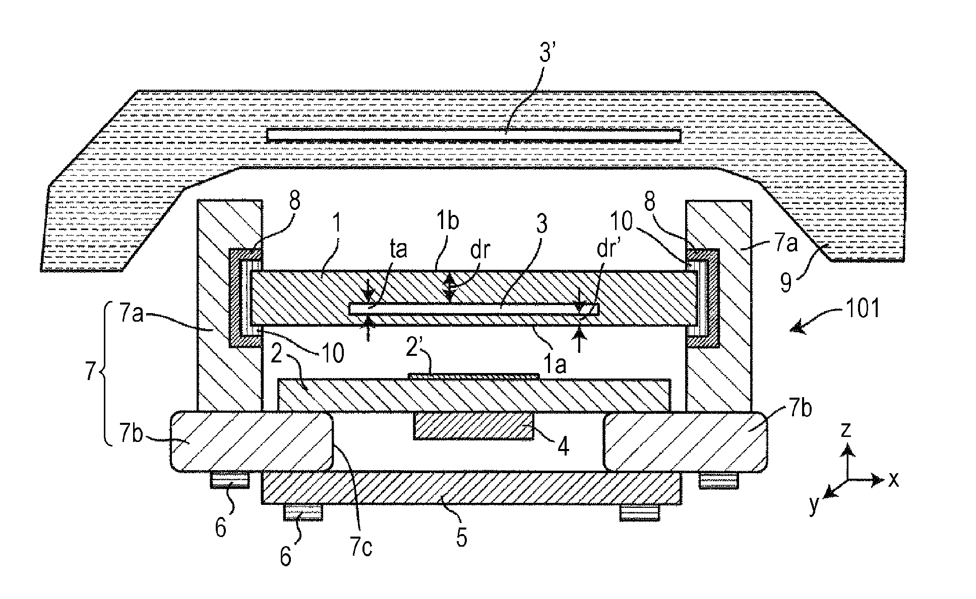
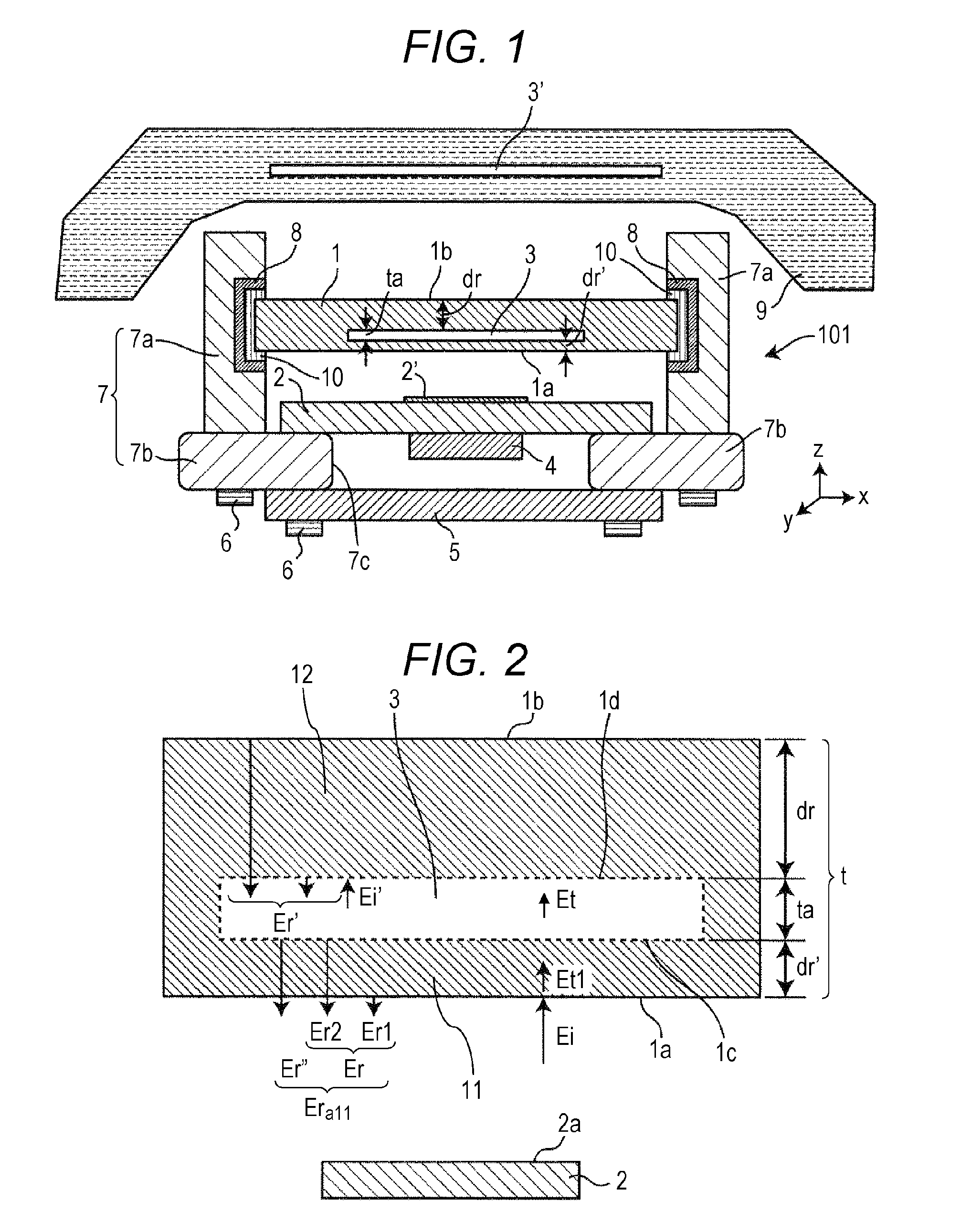
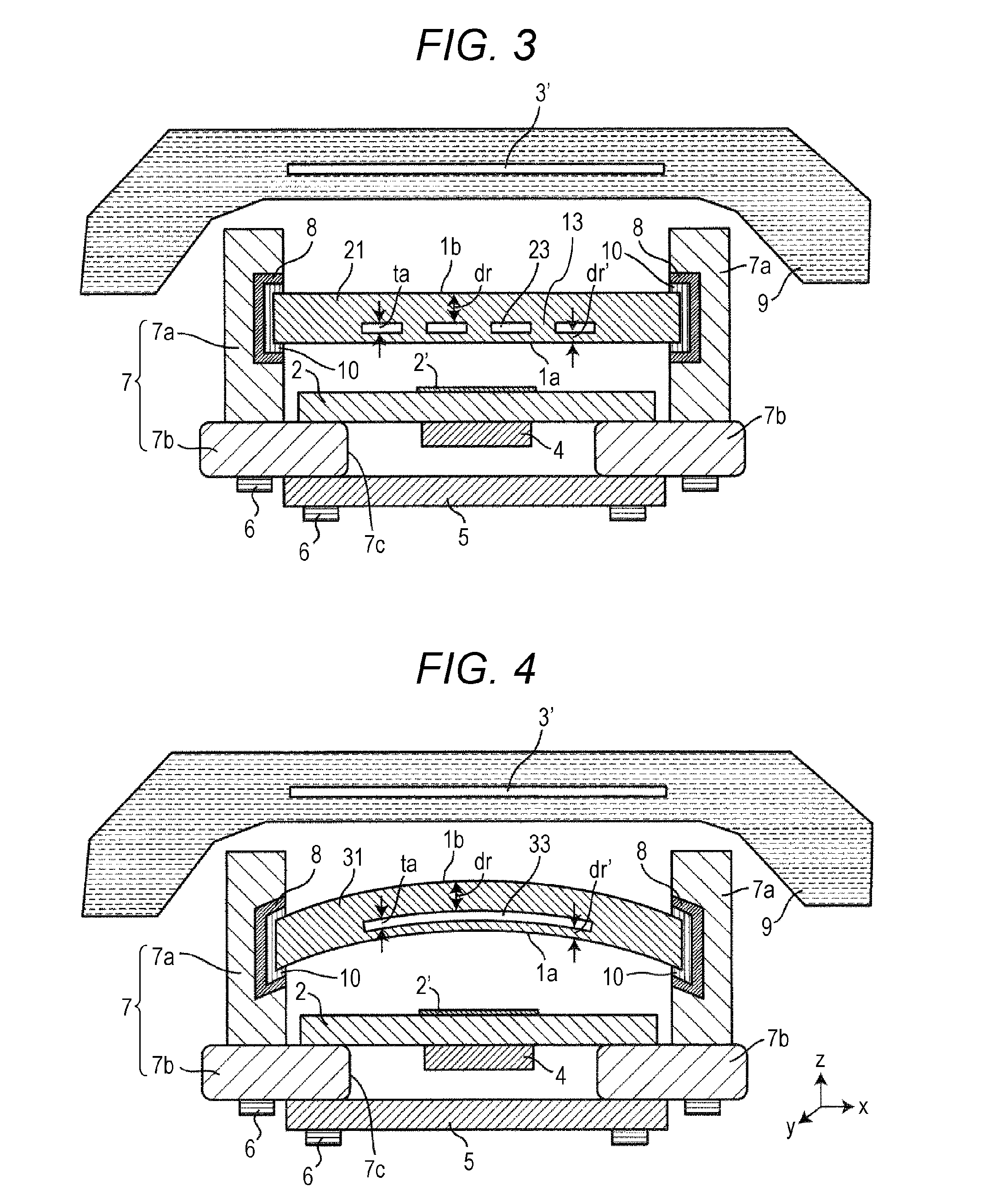
[0075]FIG. 3 is a cross-sectional view illustrating a configuration of an antenna for vehicle according to a second exemplary embodiment of the present disclosure. The antenna for vehicle of the second exemplary embodiment is formed in a similar manner to the antenna for vehicle of the first exemplary embodiment, except for a structure of radome 21. Radome 21 of the second exemplary embodiment differs from radome 1 of the first exemplary embodiment in that support 13 for maintaining space between first area 11 and second area 12 is provided within gap 23. Support 13 inhibits gap 23 provided in radome 21 from reducing mechanical strength of radome 23. Accordingly, support 13 may be formed of a plurality of cylinders, or may be grid-pattern bulkheads. When support 13 is bulkheads, gap 23 will be divided into a plurality of portions. In radome 21 of the antenna for vehicle of the second exemplary embodiment, thickness dr′ of first area 11, thickness dr of second area 12, and clearance ...

third exemplary embodiment

[0077]FIG. 4 is a cross-sectional view illustrating a configuration of an antenna for vehicle according to a third exemplary embodiment of the present disclosure. The antenna for vehicle of the third exemplary embodiment is formed in a similar manner to the antenna for vehicle of the first exemplary embodiment, except for a structure of radome 31. Radome 31 of the third exemplary embodiment differs from radome 1 of the first exemplary embodiment in that radome 31 is formed in a curved shape projecting forward. In radome 31 of the antenna for vehicle of the third exemplary embodiment, thickness dr′ of first area 11, thickness dr of second area 12, and clearance to of gap 33 are set in a similar manner to radome 1 of the first exemplary embodiment.

[0078]Radome 31 of the third exemplary embodiment configured as described above can inhibit degradation of an antenna characteristic in a similar manner to radome 1 of the first exemplary embodiment, and can further reduce characteristic deg...


PUM


Abstract

An millimeter wave antenna includes an antenna body adapted to transmit and receive an electromagnetic wave of a millimeter wave band; and a radome that covers a transmitting and receiving surface of the antenna body. The transmitting and receiving surface and the radorm are apart from each other and have a space therebetween. The radome includes a gap adapted to allow the electromagnetic wave of the millimeter wave band to pass through the gap. A radar apparatus for vehicle includes the millimeter wave antenna.

Description

BACKGROUND[0001]1. Technical Field[0002]The present disclosure relates to a millimeter wave antenna and a radar apparatus for vehicle.[0003]2. Description of the Related Art[0004]Millimeter wave antennas are used for radar apparatuses for vehicle, for example. Such a radar apparatus for vehicle is mounted in a vehicle, which is a mobile unit, and detects, for example, a direction, relative distance, and relative velocity of an obstacle, such as a mobile unit running ahead.[0005]In recent years, prevention safety technologies for preventing accidents have been particularly attracting more and more attention. ACC (Adaptive Cruise Control system) that uses a 76 GHz band millimeter wave radar and ADAS (Advanced Driver Assistance System) such as a pre-crash safety system are already becoming standard equipment on luxury cars. In response to such increasing needs, standardization of a new radar band (79 GHz band) is being promoted, and the new radar band is expected to become available fr...

Claims


Application Information

Patent Timeline
IPC IPC(8): H01Q1/42H01Q1/32G01S13/88G01S13/931
CPCH01Q1/42G01S2013/9346H01Q1/32G01S13/88G01S7/03G01S13/931H01Q1/422H01Q1/3283G01S2013/93185G01S2013/93275G01S7/027
Inventor TAGI, HIROYOSHI
Owner PANASONIC INTELLECTUAL PROPERTY MANAGEMENT CO LTD
Why Eureka
Try Eureka