Torque converter

a converter and torque technology, applied in the direction of rotary clutches, fluid couplings, gearings, etc., can solve the problems of increasing the axial length of the transmission, the need for a complicated shape of the side bearing, and the complexity of the transmission mechanism

a converter and torque technology, applied in the direction of rotary clutches, fluid couplings, gearings, etc., can solve the problems of increasing the axial length of the transmission, the need for a complicated shape of the side bearing, and the complexity of the transmission mechanism

US6568180B2Inactive Publication Date: 2003-05-27AISIN AW CO LTD

Image

  • Torque converter
  • Torque converter
  • Torque converter

Examples


Embodiment Construction

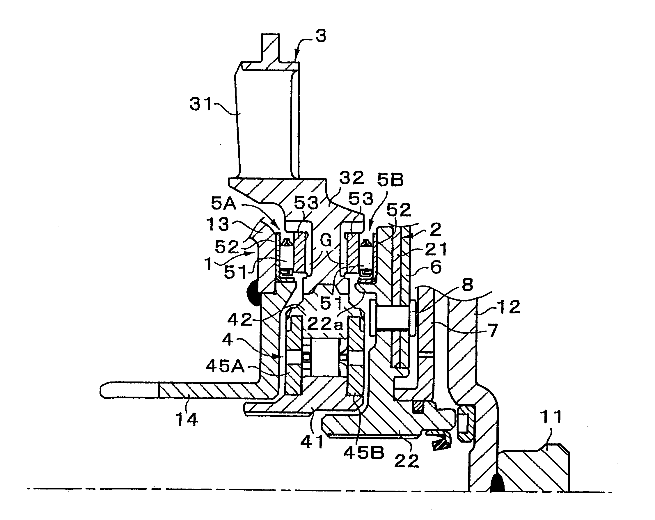
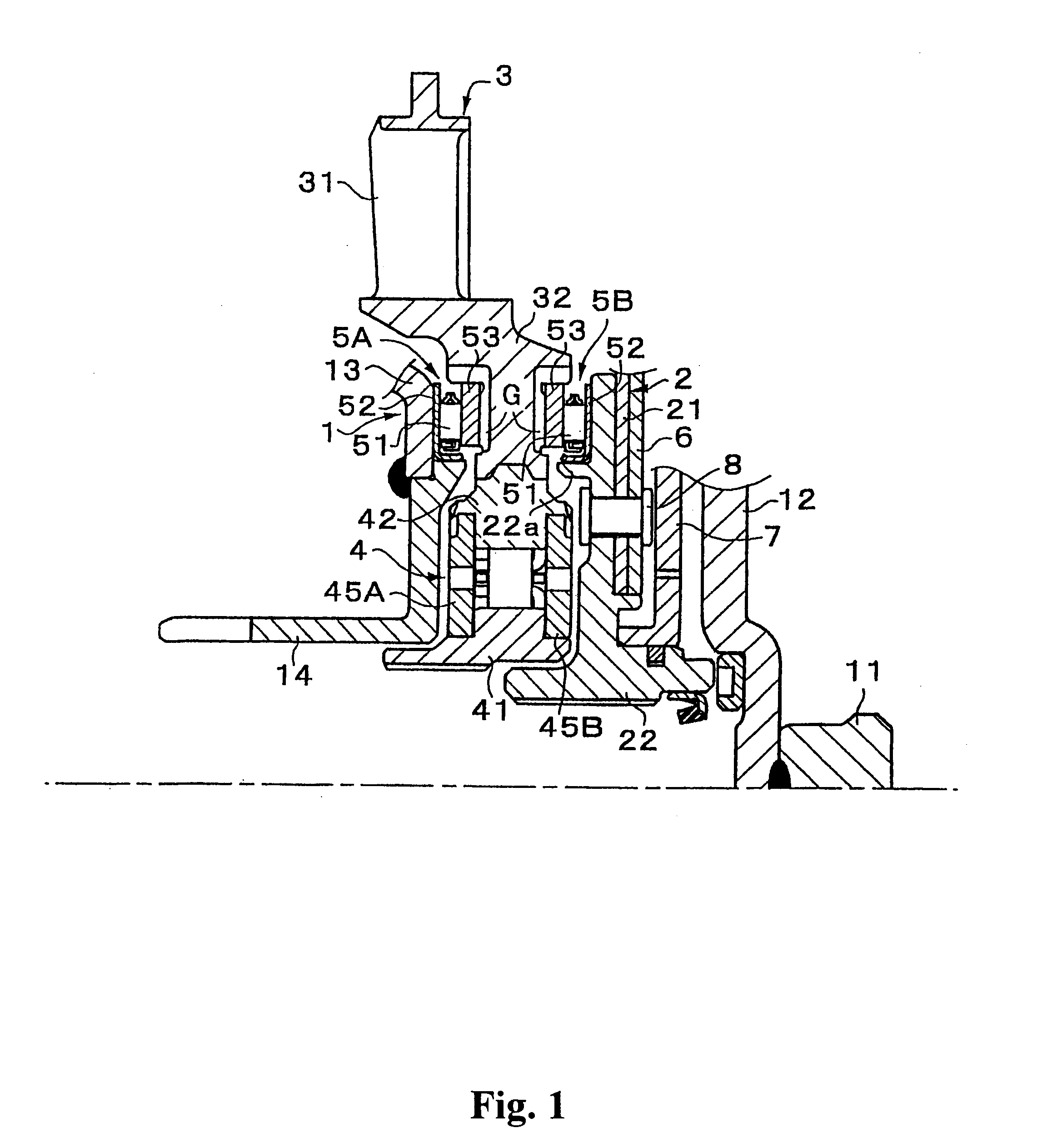
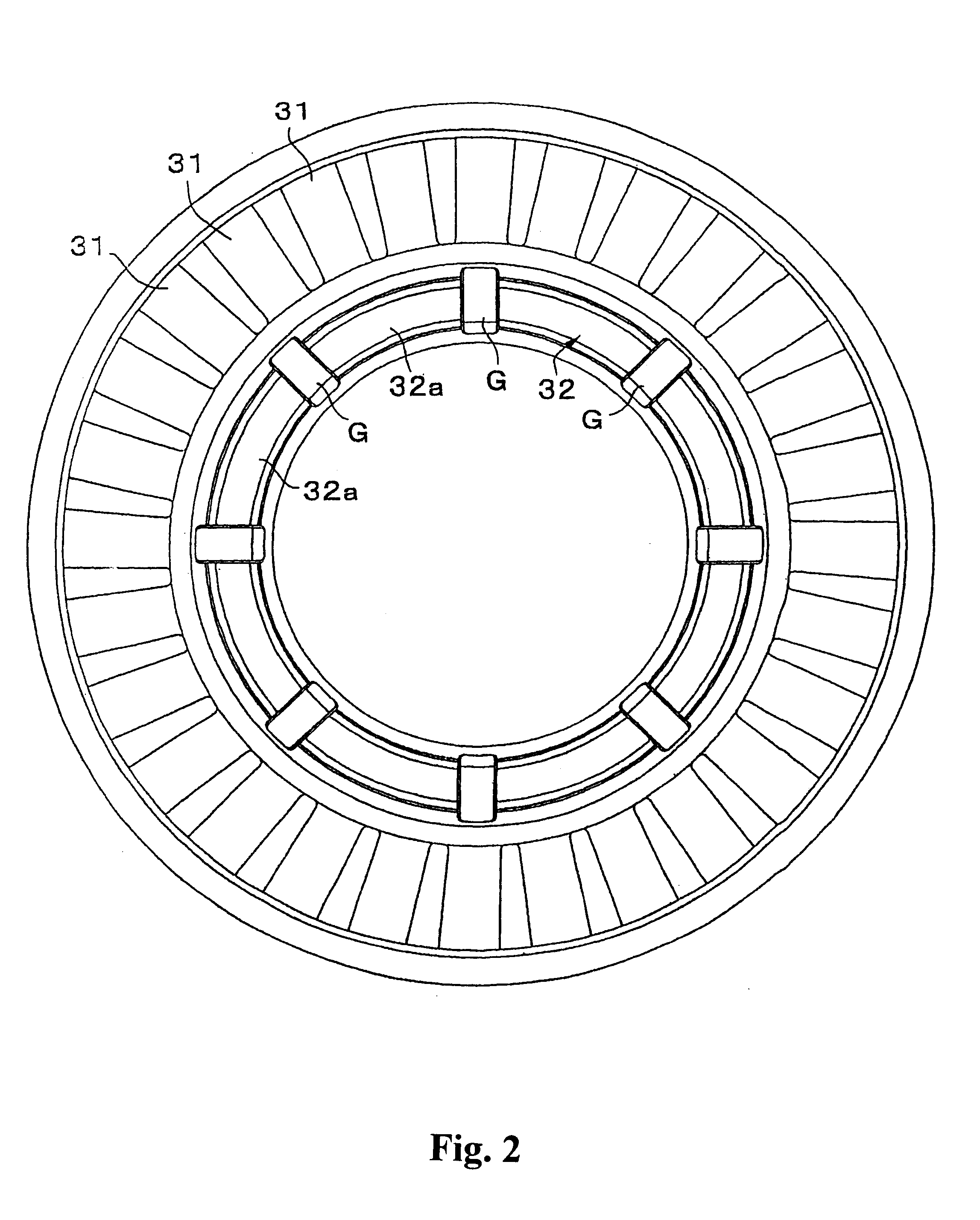
Hereinafter, exemplary embodiments of the invention will be explained with reference to the drawings. FIG. 1 is a partially sectional side view of a torque converter according to the first exemplary embodiment of the invention in which a truss and a lock-up clutch are omitted. FIG. 2 is a front view illustrating only the stator of the torque converter shown in FIG. 1. As shown in FIG. 1, similar to conventional torque converters, the torque converter comprises a one-way clutch 4 for supporting a stator 3 radially on a fixed member (not shown) in such a manner that the stator is rotatable in one way, and a pair of thrust bearings 5A, 5B for supporting the stator 3 axially between a pump impeller 1 and a turbine runner 2.

According to the invention, the diameters of the one-way clutch 4 and both the thrust bearings 5A, 5B are different, and the thrust bearings 5A, 5B do not axially overlap side bearings 45A, 45B of the one-way clutch 4. Also, in this exemplary embodiment, at least a po...


PUM


Abstract

A torque converter including a one-way clutch for supporting a stator radially on a fixed member in such a manner that the stator is rotatable in one direction, and a pair of thrust bearings for supporting the stator axially between a pump impeller and a turbine runner, wherein the diameters of the one-way clutch and both of the thrust bearings are different, and the thrust bearings do not axially overlap at least side bearings of the one-way clutch. With this arrangement, thrust force is not applied to the side bearings, and thus, the side bearings are thinner than conventional side bearings. Accordingly, the area radially inside of the stator in the torque converter is axially shortened.

Description

INCORPORATION BY REFERENCEThe disclosure of Japanese Patent Application No. 2000-183516 is incorporated herein by reference in its entirety.1. Field of InventionThe invention relates to a torque converter and, in particular, to a thrust force supporting structure of a stator thereof.2. Description of Related ArtA torque converter is generally configured to have a stator interposed between a pump impeller and a turbine runner. The stator is radially supported on an appropriate fixed member, through an annular one-way clutch, in such a manner that the stator is rotatable in one direction. At the same time, the stator is axially supported between the pump impeller and the turbine runner (in particular, its hub) through annular thrust bearings. Conventionally, the diameters of the one-way clutch and the thrust bearings for supporting the stator are substantially the same. In addition, the one-way clutch and the thrust bearings are arranged to axially overlap one another such that the on...

Claims


Application Information

Patent Timeline
27 May 2003
Publication
US6568180B2
IPC
F16H41/00; F16H41/24; F16D41/06
CPC
F16H41/24; F16H2041/246
Inventors
MAEDA, KOJI; YAMASHITA, TOMOHIRO