High-speed fluidic device

a fluidic device and high-speed technology, applied in the direction of gearing, piston pumps, hoisting equipment, etc., can solve the problems of life, vibration and noise of gears, and the inability to transmit drive power to the impeller, etc., to achieve high efficiency, high rotational speed, and high torque

Inactive Publication Date: 2006-02-07
NSK LTD
View PDF18 Cites 36 Cited by
  • Summary
  • Abstract
  • Description
  • Claims
  • Application Information

AI Technical Summary

Benefits of technology

[0015]Under such circumstances, an object of the invention is to provide a high-speed fluidic device in which high transmission efficiency can be obtained as well as quiet and smooth motive power transmission can be performed and which is high both in installability and in controllability, small in size, light in weight and low in cost. In addition to this, an object of the invention is to provide a drive device and a high-speed fluidic device in which high transmission efficiency can be obtained as well as quiet and smooth motive power transmission can be performed and in which the temperature of a friction roller type transmission can be prevented from increasing excessively as well as the axial length can be shortened remarkably to attain reduction in size.

Problems solved by technology

When the number of revolutions exceeds a value in a range of from the order of tens of thousands of rpm to the order of a hundred thousand of rpm, there is however a large problem in life as well as in vibration and noise of gears.
For this reason, slip occurs in a state of high rotational speed and high torque so that drive power cannot be transmitted to the impeller.
At the same time, there is a problem in life because an intensive pressing force always works.
As described above, in the method in which motive power is obtained by direct belt transmission from the drive shaft of the engine, the mount position of the supercharger is inevitably limited to a position on the same plane with a pulley mounted on a crankshaft of the engine.
On the other hand, an engine room is much crowded with the recent advance of functionalization of the engine, electronic application to an automobile, security safeguards against collision of a vehicle body, and so on.
There is no degree of freedom for the installation position of the supercharger.
It is however difficult to optimize these distances and installation position because the installation position of the supercharger is limited for the aforementioned reason.
As a result, if the supercharger is designed so that a sufficient supercharging effect can be obtained even in the case where the engine rotates at a low speed, there is a disadvantage in that the quantity of supply air and boost pressure become too large inevitably when the engine rotates at a high speed.
In this method, there is however a problem that the system is complicated to bring increase in weight, volume and cost.
A large part of the loss makes a heat loss.
This heat loss is added to a heat loss of the electric motor.
Furthermore, a larger amount of heat is generated in a supercharger for large exhaust capacity engine or a supercharger high in supercharging pressure.

Method used


Image

  • High-speed fluidic device
  • High-speed fluidic device
  • High-speed fluidic device

Examples


first embodiment

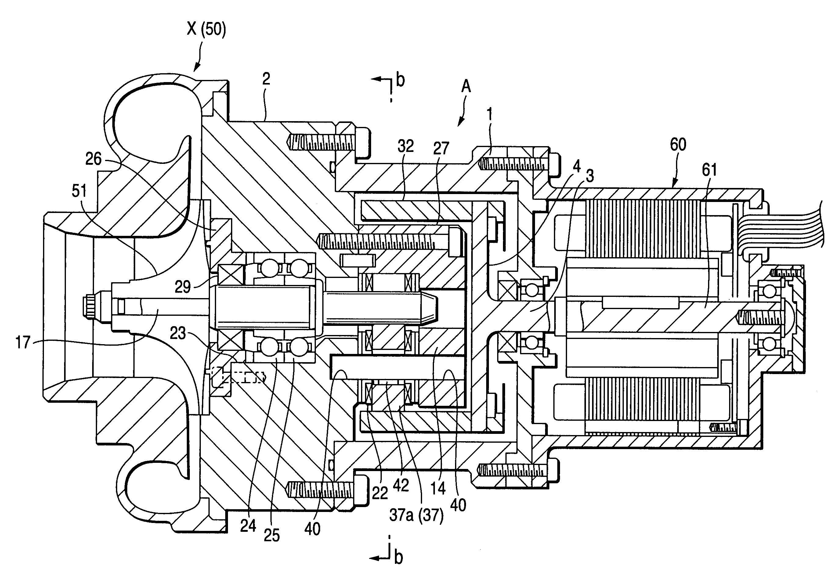
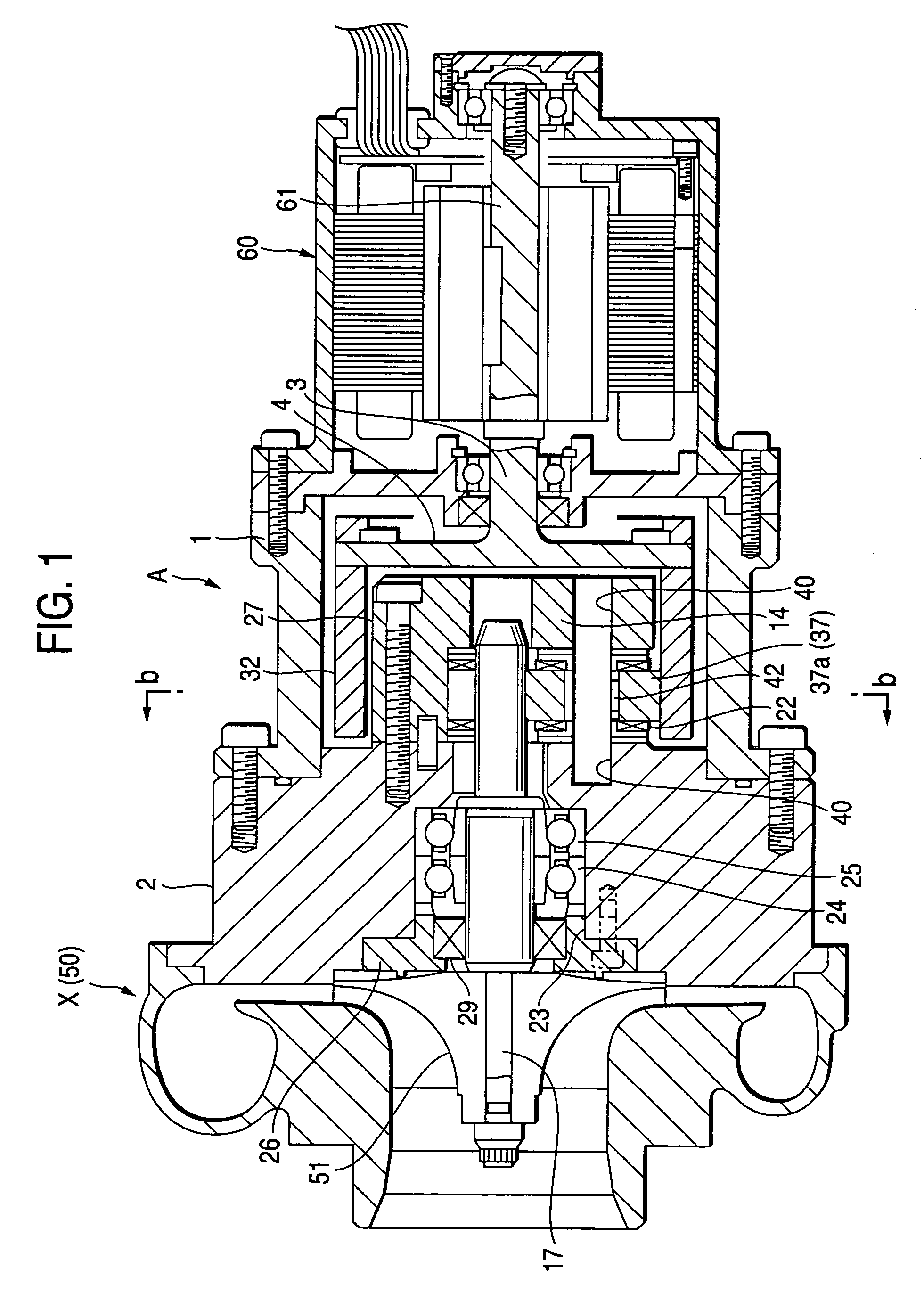
[0095]Further, in this embodiment, the supercharger 50 is used as the high-speed fluidic machine X. The impeller 51 of the supercharger 50 is mounted on an end portion of the high-speed side shaft 17. The drive shaft 61 of the electric motor 60 is integrally connected to the other end portion of the high-speed side shaft 17. The configuration, operation and effect of this embodiment in this case are equivalent to those of the

[0096]Further, this embodiment can be applied not only to the engine supercharger but also to a ventilator for feeding hydrogen as fuel, a blower for blowing out water and water vapor produced by a reaction of hydrogen and oxygen, and so on, for example, in a vehicle powered by fuel battery.

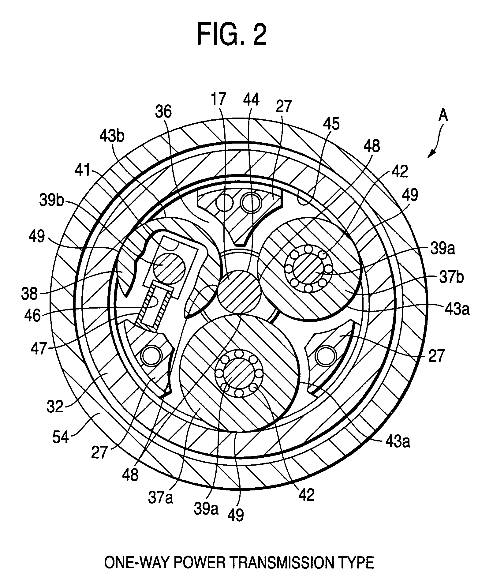
[0097]FIG. 7 is a sectional view of a wedge roller type transmission according to a third embodiment of the invention. A sectional view taken along the line b—b, of the wedge roller type transmission will be omitted because it is equivalent to FIG. 2 or 4. Parts the same as t...

sixth embodiment

[0114]FIG. 10 is a vertical sectional view of a high-speed fluidic device according to the invention.

[0115]In this embodiment, as shown in FIG. 10, a supercharger 60 is used as the high-speed fluidic machine X. An impeller 61 of the supercharger 60 is mounted on an end portion of the high-speed side shaft 17. Incidentally, a housing 62 is formed around the impeller 61, an intake port 63 is provided in the axial outside of the impeller 61, and a scroll-shaped supercharging passage 64 is formed in the radial outside of the impeller 61.

[0116]The high-speed side shaft 17 is sealed with a mechanical seal 65 between the impeller 61 and the bearings 56 and 57.

[0117]An electric motor M as a drive source is shaped like a cylinder. The electric motor M includes a cylindrical stator 71 disposed in the housing 1, and a cylindrical rotor 72 rotated by the stator 71.

[0118]Incidentally, the housing 1 is formed so that a cooling water (oil) supply unit 73 can be connected to an upper portion of the...

seventh embodiment

[0130]FIG. 11 is a vertical sectional view of a high-speed fluidic device according to the invention.

[0131]In this embodiment, as shown in FIG. 11, an oil seal 66 is used as a substitute for the mechanical seal 65.

[0132]That is, the high-speed side shaft 17 is sealed with the oil seal 66 between the impeller 61 and the bearings 56 and 57.

[0133]The other configuration, operation and effect of this embodiment are equivalent to those of the sixth embodiment.


PUM


Abstract

A high-speed fluidic device has a friction roller type speed-increasing mechanism, an electric motor, and a high-speed fluidic machine, wherein: the friction roller type speed-increasing mechanism includes a housing, a low-speed side member having an outer ring provided at one end portion thereof, a high-speed side shaft rotatably supported by the housing so as to be eccentric to the low-speed side member and the outer ring, at least one guide roller rotatably supported between the outer ring and the high-speed side shaft, and at least one movable roller rotatably supported between the outer ring and the high-speed side shaft; the electric motor drives the friction roller type speed-increasing mechanism; and the high-speed fluidic machine is connected to the high-speed side shaft so as to be driven by the high-speed side shaft.

Description

BACKGROUND OF THE INVENTION[0001]1. Field of the Invention[0002]The present invention relates to a high-speed fluidic device for pouring a fluid by high-speed rotation and particularly to a high-speed fluidic device including a high-speed fluidic machine such as a turbo machine, a supercharger or a ventilator.[0003]2. Description of the Related Art[0004]As a high-speed fluidic device, a supercharger for vehicle engine has been heretofore disclosed, for example, in JP-A-4-203421 and JP-A-11-294548. The supercharger is of a centrifugal type in which motive power is directly belt-transmitted from a drive shaft of an engine to a speed-increasing mechanism to increase speed to thereby drive an impeller of the speed-increasing mechanism to rotate.[0005]In the device disclosed in JP-A-4-203421, a planetary gear mechanism is used to make the speed-increasing rate of the speed-increasing mechanism high. When the number of revolutions exceeds a value in a range of from the order of tens of th...

Claims


Application Information

Patent Timeline
Patent Type & Authority Patents(United States)
IPC IPC(8): F04B17/03F02B33/40F16H13/04F16H13/10F04D13/02F04D13/06
CPCF04D13/021F04D13/06F04D13/028F04D25/02F04D25/028F04D25/06
Inventor DAIROKUNO, SATOSHINAWAMOTO, TAIKOUITOH, HIROYUKIOKANO, HIDEOBABA, TAKASHI
Owner NSK LTD
Why Eureka
Try Eureka