Permanent magnet biased inner rotor radial magnetic bearing

A technology of permanent magnet bias and inner rotor, applied in the direction of bearings, shafts and bearings, mechanical equipment, etc., can solve the problems of serious radial magnetic bearing coupling, large excitation current, multi-magnetic electromotive force, etc., to ensure the stability of operation , The effect of reducing the axial size and saving the control circuit

Inactive Publication Date: 2005-09-14
BEIHANG UNIV
View PDF0 Cites 37 Cited by
  • Summary
  • Abstract
  • Description
  • Claims
  • Application Information

AI Technical Summary

Problems solved by technology

However, the current permanent magnet bias inner rotor radial magnetic bearing structure mainly has the following types: one is to place permanent magnets on the electromagnetic magnetic circuit on the basis of ordinary radial electromagnetic bearings, so that the magnetic flux generated by the control coil needs to be Through the interior of the permanent magnet, because the permanent magnet has a large reluctance, the control coil needs a large excitation current to generate a certain electromagnetic flux. The second is to connect the permanent magnet directly to the stator laminated core, so that the permanent magnetic circuit When passing through the stator core, too much magnetomotive force will be lost, which will greatly weaken the attraction force of the permanent magnet to the rotor shaft. The third is that the stator core spans the left and right ends of the magnetic bearing, and the stator magnetic poles are pole spaced. Coils are wound on each stator core, and the permanent magnet is connected to the rotor core through a magnetically conductive ring. This structure can make the electric excitation magnetic circuit not pass through the permanent magnet, and can also prevent the permanent magnet from being directly connected with the laminated core, but The electric excitation magnetic circuit has serious coupling in the X direction and Y direction, which will make the control of the magnetic bearing more difficult. The fourth is that a stator core forms 4 magnetic poles, and 2 stator cores form 8 magnetic bearings at the left and right ends. The magnetic poles and permanent magnets are connected to the stator core through the outer magnetic ring, and each stator core is wound with coils. This structure can also make the electric excitation magnetic circuit not pass through the permanent magnets, and avoid the direct contact between the permanent magnets and the laminated stator. The iron core is connected, but because the electric excitation magnetic circuit still has serious coupling in the X direction and the Y direction, it will also increase the difficulty of the control of the magnetic bearing.
In view of the above reasons, the existing permanent magnet bias inner rotor radial magnetic bearing has the disadvantage of severe coupling in the X direction and the Y direction

Method used


Image

  • Permanent magnet biased inner rotor radial magnetic bearing
  • Permanent magnet biased inner rotor radial magnetic bearing
  • Permanent magnet biased inner rotor radial magnetic bearing

Examples


Embodiment Construction

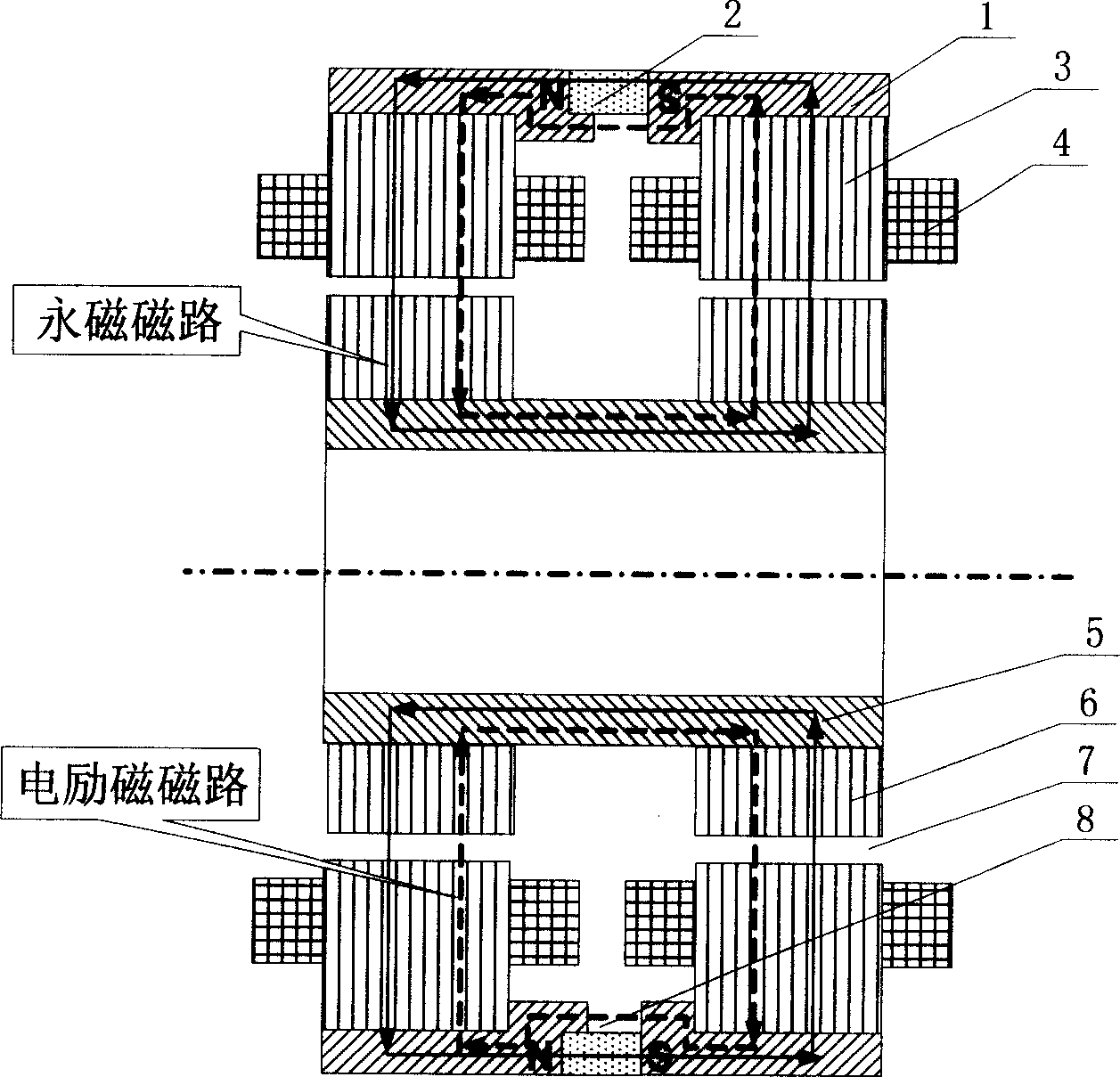
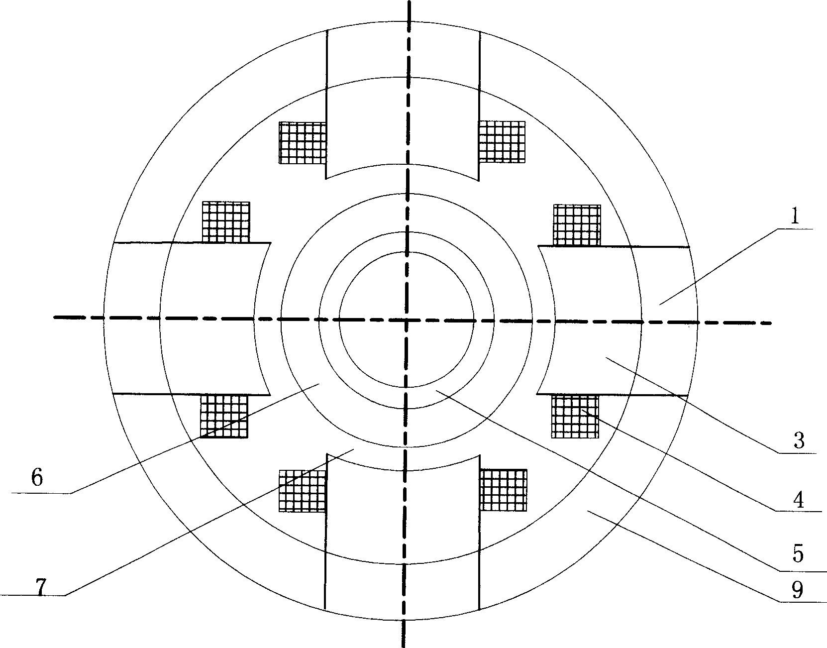
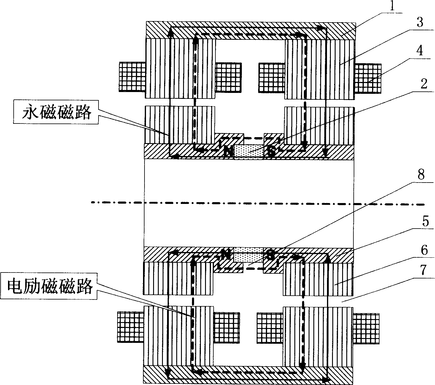
[0014] Such as figure 1 , 2 As shown, it is the outer magnetic steel of one of the technical solutions of the present invention, the outer magnetic coil permanent magnet bias inner rotor radial magnetic bearing, which is the basic form of the present invention, and it consists of 2 outer conducting magnets 1, 1 permanent magnet 2, 8 stator cores 3, 8 outer spacer magnets 9, 8 excitation coils 4, 1 inner magnetic ring 5, 2 rotor cores 6, 4 stator cores 3 form 4 in the X and Y directions 8 stator poles, 8 stator cores 3 form the stator poles in the X and Y directions at the left and right ends of the magnetic bearing, and 8 outer spaced magnets 9 connect the stator cores 3 in the X and Y directions at the left and right ends of the magnetic bearing, and each stator The magnetic poles are wound with excitation coils 4, the outside of the stator core 3 is an external conduction magnet 1, the permanent magnet 2 is located between the two external conduction magnets 1, and a second...


PUM


Abstract

The invention relates to a permanent magnet bias inner rotor radial magnetism bearing that is made up of out magnetizer, out magnetism separator, exciting winding, inner magnetizer, rotor iron core. Four stator iron cores form four magnetic poles and are connected with each other by out magnetism separator. Eight stator iron core forms eight magnetic poles and every stator magnetic pole has exciting winding. Outside the stator iron core is out magnetizer that is connected to stator iron core. The permanent magnet is located between the two out magnetizers. Inner the stator iron core is rotator iron core. And there is clearance between the inner surface of the stator iron core and the out surface of the rotator iron core. The second clearance exists between the out magnetizer and the permanent magnet to form electric excitation circuit. The invention has the advantage of reliability and easy to be controlled.

Description

Technical field [0001] The invention relates to a non-contact magnetic suspension bearing, in particular to a permanent magnetic bias inner rotor radial magnetic bearing, which can be used as a non-contact support for rotating parts in mechanical equipment such as motors and machine tools. Background technique [0002] Magnetic suspension bearings are divided into pure electromagnetic bearings and hybrid magnetic suspension bearings with permanent magnetic bias and electromagnetic control. The former uses large current and consumes a lot of power, and the hybrid magnetic suspension bearings with permanent magnetic bias and electromagnetic control. The magnetic field generated by the permanent magnet bears the main load. Bearing capacity, the electromagnetic field provides auxiliary adjustment bearing capacity, so this kind of bearing can greatly reduce the control current and reduce the loss. However, the current permanent magnet bias inner rotor radial magnetic bearing stru...

Claims


Application Information

Patent Timeline
Patent Type & Authority Applications(China)
IPC IPC(8): F16C32/04
CPCF16C32/0465F16C32/0468F16C32/0487
Inventor 房建成孙津济马善振
Owner BEIHANG UNIV
Why Eureka
Try Eureka