Turbocharger compressor wheel having a counterbore treated for enhanced endurance to stress-induced fatigue and configurable to provide a compact axial length

a compressor wheel and counterbore technology, applied in the direction of blade accessories, machines/engines, waterborne vessels, etc., can solve the problems of excessive high tensile stress in the bore area, and shortened wheel life, so as to avoid or reduce overhang improve the life of the compressor wheel, and enhance endurance

Inactive Publication Date: 2006-02-07
GENERAL ELECTRIC CO
View PDF8 Cites 35 Cited by
  • Summary
  • Abstract
  • Description
  • Claims
  • Application Information

AI Technical Summary

Benefits of technology

[0005]Aspects of the present invention propose to improve compressor life by using a hub with a counterbore including a base surface treated to impart residual compressive stresses for enhanced endurance to stress-induced fatigue. The surface treatment allows extending the counterbore relatively closer to a plane indicative of typical maximum stress. This design flexibility advantageously allows avoiding or reducing overhang of the compressor wheel, thereby improving rotor dynamics and reducing the axial length of the hub, and the overall foot print of the compressor wheel and turbocharger.
[0006]Generally, the present invention fulfills the foregoing needs by providing in one aspect thereof, a method of manufacturing a compressor wheel. The method allows providing a hub extension of the compressor wheel that defines a counterbore. The method further allows imparting residual compressive stresses to a base surface of the counterbore.

Problems solved by technology

The high boost ratios, typically 3.8 or higher, may require high tip speeds on a turbocharger compressor wheel, which may lead to high levels of tensile stress in a bore area and shortened wheel life due to low cycle fatigue.
Since the length of the shaft / threaded interface is generally constant for any given application, the foregoing arrangement (that causes the designer to position such an interface away from the high stress plane) may result in excessive overhang of the compressor wheel.
This detrimentally affects rotor dynamics and increases the axial length of the hub extension, thus increasing the overall footprint of the compressor wheel and turbocharger.

Method used


Image

  • Turbocharger compressor wheel having a counterbore treated for enhanced endurance to stress-induced fatigue and configurable to provide a compact axial length
  • Turbocharger compressor wheel having a counterbore treated for enhanced endurance to stress-induced fatigue and configurable to provide a compact axial length
  • Turbocharger compressor wheel having a counterbore treated for enhanced endurance to stress-induced fatigue and configurable to provide a compact axial length

Examples


Embodiment Construction

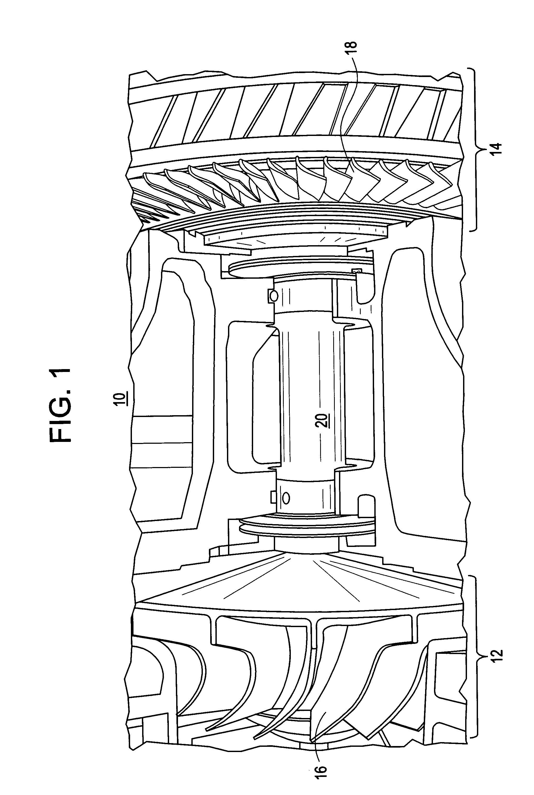
[0013]FIG. 1 shows a cutaway view of an exemplary turbocharger 10 that may benefit from the teachings of the present invention. Turbocharger 10 generally comprises respective compressor and turbine stages 12 and 14 including a compressor wheel 16 and a turbine wheel 18 coupled through a rotatable shaft 20. The turbine wheel 18 is disposed within a turbine housing, which includes an inlet for receiving exhaust gases from an internal combustion engine (not shown). The turbine housing guides the engine exhaust gases for communication with and expansion through the turbine wheel 18 for rotatably driving the turbine wheel. Simultaneously, the turbine wheel rotatably drives the shaft 20 and compressor wheel 16, as may be disposed within a compressor housing. The compressor wheel 16 and housing allow drawing in and compressing ambient air for supply to the intake of the engine.

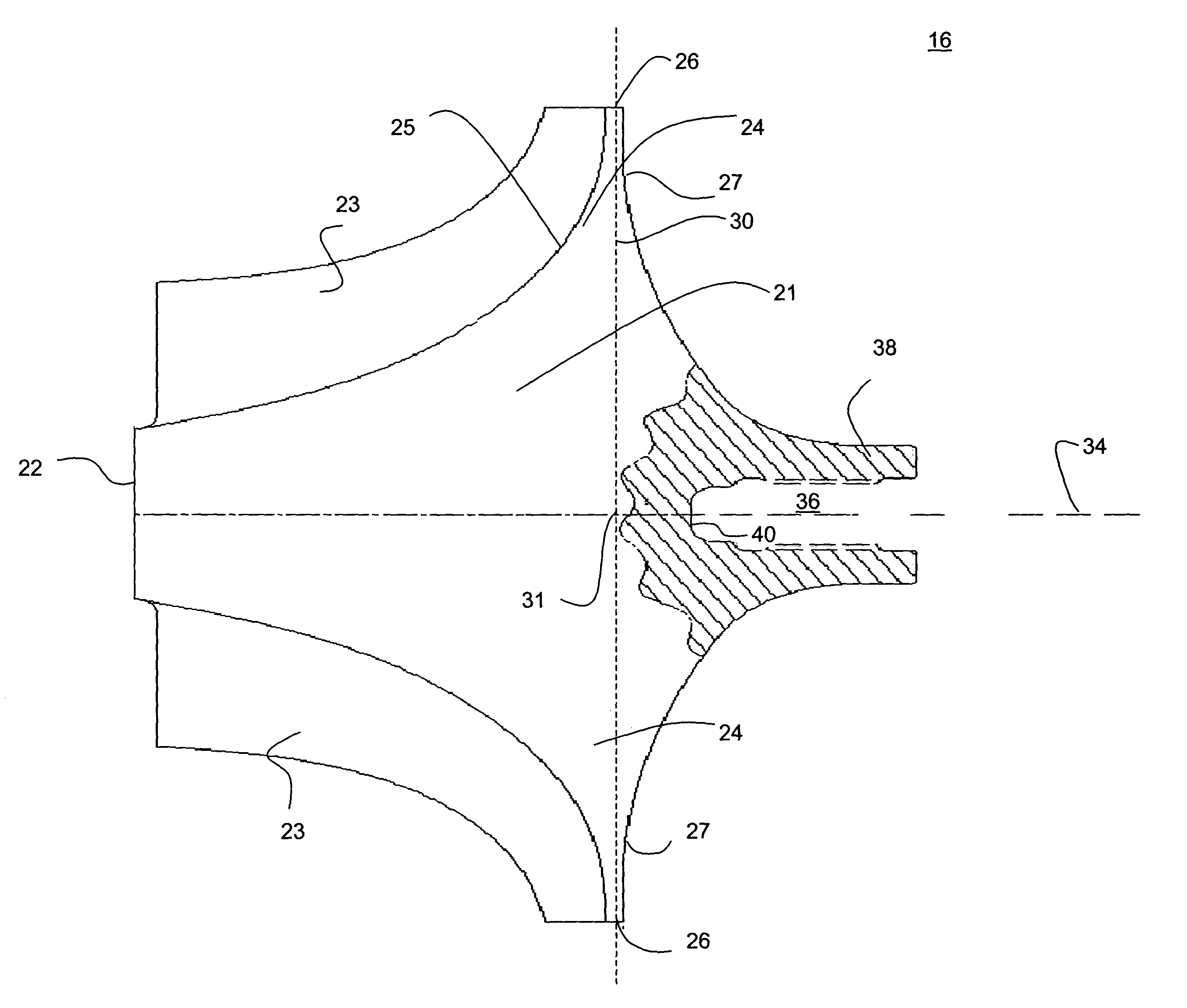
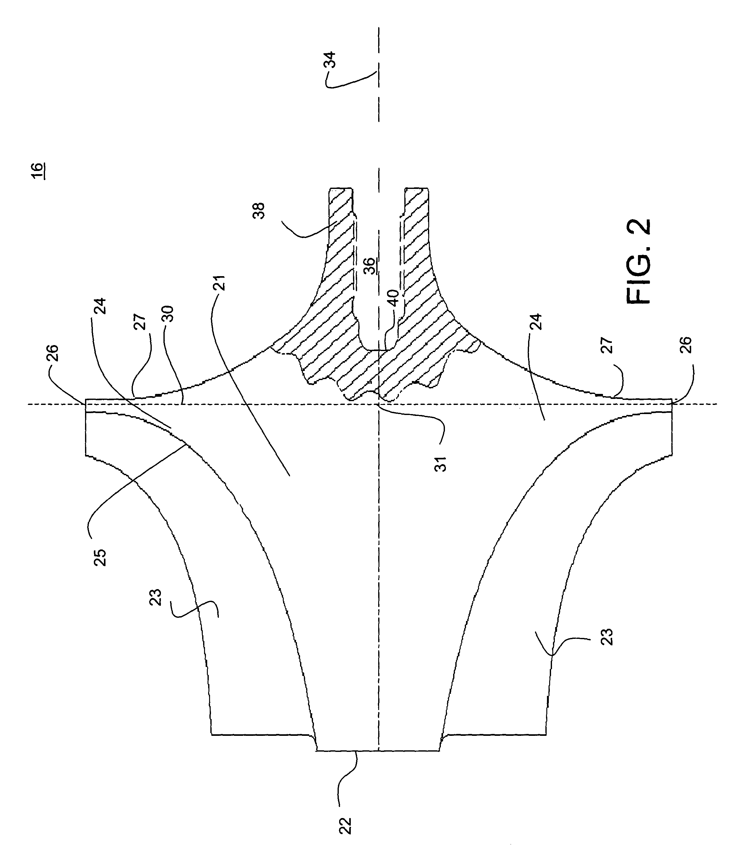
[0014]Referring to FIG. 2, a cross-sectional view of an exemplary embodiment of the compressor wheel 16 is shown. ...


PUM

PropertyMeasurementUnit
tensile stressaaaaaaaaaa
residual compressive stressesaaaaaaaaaa
axial lengthaaaaaaaaaa

Abstract

Compressor wheel and techniques for manufacturing such a wheel are provided. The wheel may include a hub with a counterbore internally treated to impart residual compressive stresses for enhanced endurance to stress-induced fatigue. The surface treatment allows extending the counterbore relatively closer to a plane of typical maximum stress of the wheel. This design flexibility advantageously allows avoiding or reducing overhang of the compressor wheel, thereby improving rotor dynamics and reducing the axial length of the hub, and the overall foot print of the compressor wheel.

Description

BACKGROUND OF THE INVENTION[0001]This invention relates generally to compressor wheels or impellers as may be used in a turbocharger, supercharger, and the like.[0002]Locomotives equipped with internal combustion engines, e.g., diesel engines, designed to meet stringent emissions regulations may require relatively high air flow rates and high manifold pressures, as may be provided by a turbocharger, to meet air quality targets while maximizing fuel economy and reliability. The high boost ratios, typically 3.8 or higher, may require high tip speeds on a turbocharger compressor wheel, which may lead to high levels of tensile stress in a bore area and shortened wheel life due to low cycle fatigue. It is known that compressor wheels have used a through bore that extends through the center of the wheel along a rotation axis, and where the wheel may be securely mounted onto a shaft with a locking nut.[0003]It is further known that so called boreless compressor wheels are able to rotate at...

Claims


Application Information

Patent Timeline
Patent Type & Authority Patents(United States)
IPC IPC(8): F04D29/20B23P9/00B23P9/02B23P15/00B24B39/02C21D7/06C21D7/08C21D10/00F01D5/02F02C6/12F04D29/26F04D29/28
CPCB23P9/00B23P9/02B23P15/006B24B39/02C21D7/06F01D5/025F04D29/266F04D29/284C21D7/08Y10T29/47F05D2220/40Y10T29/49236C21D10/005
Inventor FURMAN, ANTHONY HOLMESSWENSON, KENDALL ROGERLORINGER, DANIEL EDWARD
Owner GENERAL ELECTRIC CO
Why Eureka
Try Eureka