Vehicle drive device

a drive device and vehicle technology, applied in the direction of rotary clutches, fluid couplings, gearings, etc., can solve the problems of increasing the size of the entire device, and achieve the effect of improving the manufacturability of the drive device for the vehicle, efficient cooling of the engagement member, and improving the oil passage structur

Active Publication Date: 2014-01-07
AISIN AW CO LTD +1
View PDF56 Cites 36 Cited by
  • Summary
  • Abstract
  • Description
  • Claims
  • Application Information

AI Technical Summary

Benefits of technology

[0005]Therefore, it is desired to realize a drive device for a vehicle that can appropriately supply oil to an operating oil pressure chamber of an engagement device and can rotatably support a rotor member of a rotary electric machine appropriately, and that can be downsized as a whole by further reducing an axial length of the device.

Problems solved by technology

As a result, there has been a problem that an axial length increases by that amount, inevitably resulting in an increase in the size of the entire device.

Method used


Image

  • Vehicle drive device
  • Vehicle drive device
  • Vehicle drive device

Examples


Embodiment Construction

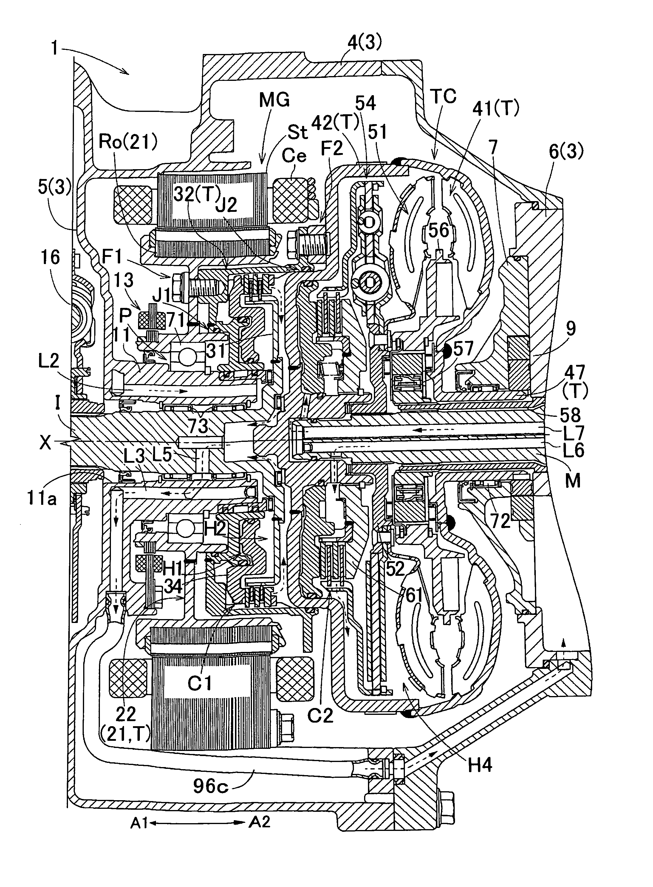
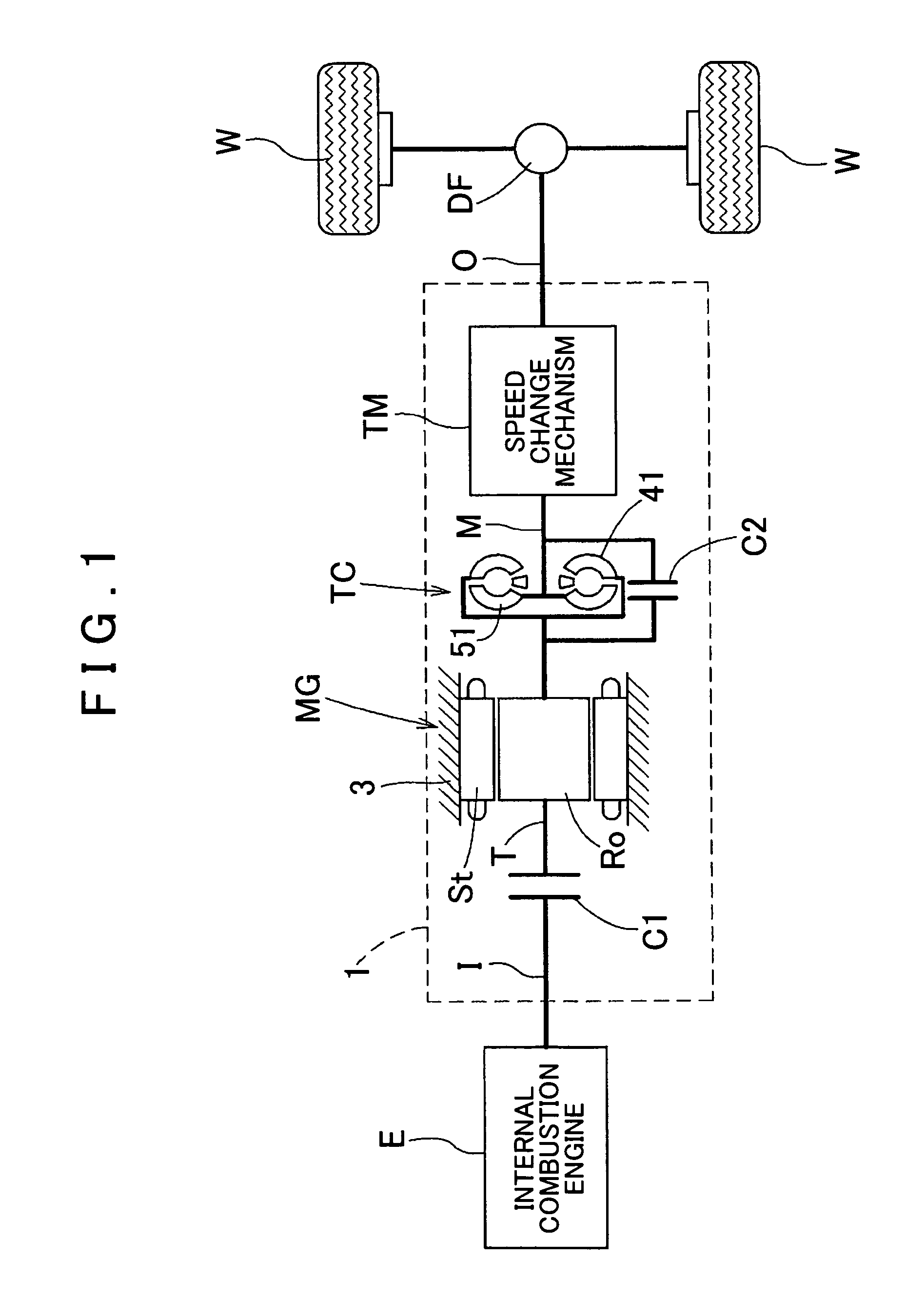
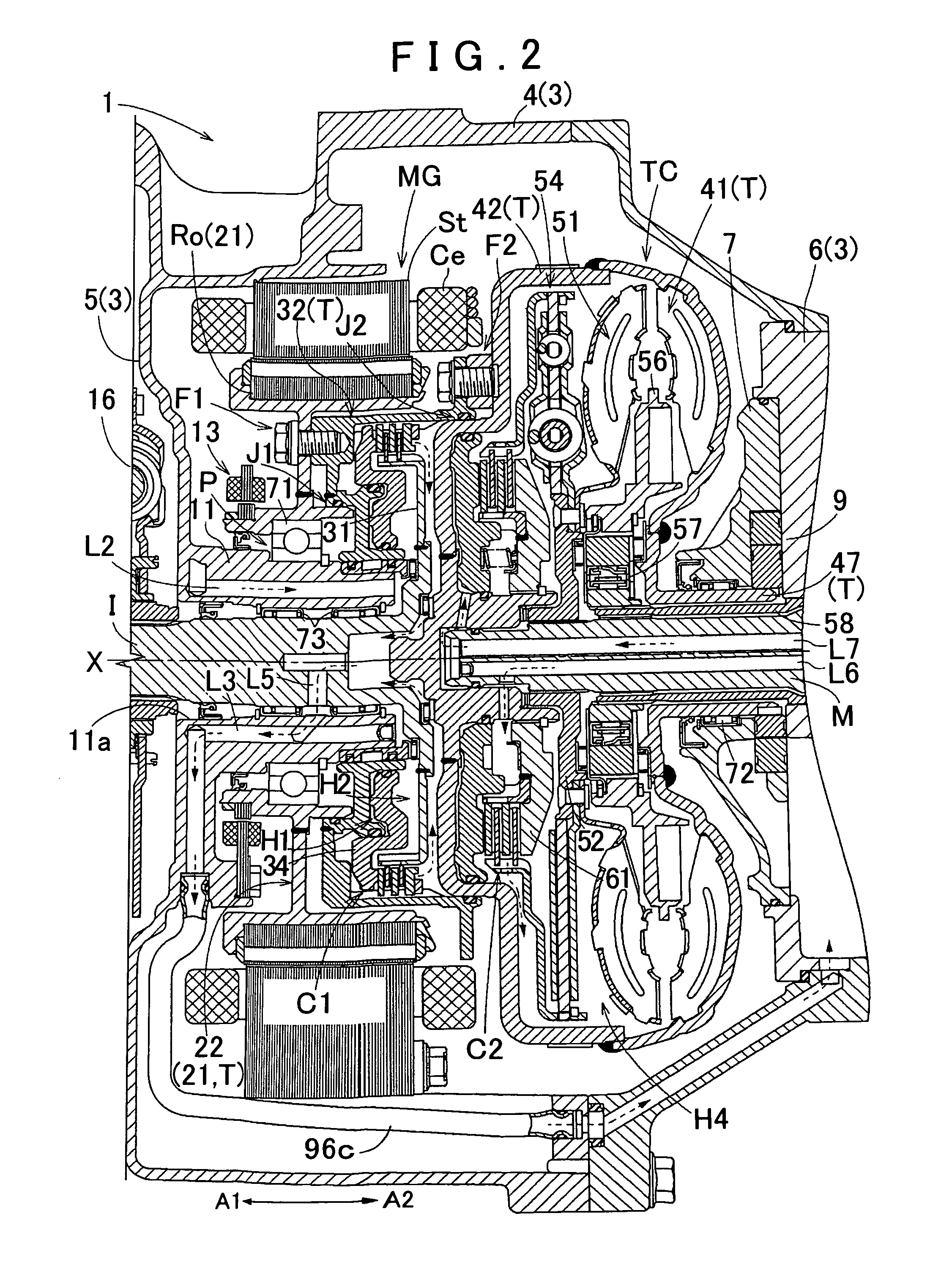
[0042]An embodiment of the present invention will be described with reference to the accompanying drawings. As shown in FIG. 1, the drive device 1 is a drive device for a hybrid vehicle (hybrid drive device) that uses one or both of an internal combustion engine E and a rotary electric machine MG as a source of vehicle driving force. The drive device 1 is structured as a drive device for a so-called one-motor parallel type hybrid vehicle. The drive device 1 according to the present embodiment will be described below in detail.

1. Overall Structure of Drive Device

[0043]First of all, an overall structure of the drive device 1 according to the present embodiment will be described. As shown in FIG. 1, the drive device 1 is provided with an input shaft I drivingly connected to the internal combustion engine E serving as a first source of driving force of the vehicle, an output shaft O drivingly connected to wheels W, the rotary electric machine MG serving as a second source of driving for...


PUM


Abstract

A drive device for a vehicle configured between an internal combustion engine and a wheel. The drive device includes a rotary electric machine, and an engagement device connecting the drive device to the engine by a fluid coupling using hydraulic pressure. A case houses at least a portion of the drive device and includes a support wall extending radially, and a cylindrical projecting portion projecting from the support wall toward a side in an axial second direction that is in a direction opposite to the axial first direction. The engagement device includes an operating oil pressure chamber supplied with the hydraulic pressure. A rotor member of the rotary electric machine is radially supported by the cylindrical projecting portion in a rotatable state via a support bearing. The cylindrical projecting portion is formed with an operating oil supply passage supplying oil to the operating oil pressure chamber.

Description

INCORPORATION BY REFERENCE[0001]The disclosure of Japanese Patent Applications No. 2010-246512 filed on Nov. 2, 2010, No. 2009-264381 filed on Nov. 19, 2009, No. 2010-049192 filed on Mar. 5, 2010, and No. 2010-049193 filed on Mar. 5, 2010, including the specification, drawings and abstract is incorporated herein by reference in its entirety.BACKGROUND OF THE INVENTION[0002]The present invention relates to a drive device for a vehicle equipped with an input member drivingly connected to an internal combustion engine, an output member drivingly connected to a wheel, a rotary electric machine, a fluid coupling drivingly connected to the rotary electric machine, an engagement device selectively drivingly connecting the input member with the rotary electric machine and the fluid coupling, and a case housing at least the rotary electric machine, the engagement device, and the fluid coupling.DESCRIPTION OF THE RELATED ART[0003]As a drive device for a vehicle such as those described above, ...

Claims


Application Information

Patent Timeline
Patent Type & Authority Patents(United States)
IPC IPC(8): F16D47/06B60K6/387H02K7/108F16D25/0638
CPCF16H2045/0284F16H2045/0226F16H2045/002B60K6/48B60K6/405F16H45/02B60K6/26Y02T10/6221F16H2045/021Y02T10/62B60K17/06F16H57/04
Inventor IWASE, MIKIOSUZUKI, TOMOHIDEJINNAI, NAOYAOKISHIMA, TATSUYAKAMIYA, TOSHIHIKO
Owner AISIN AW CO LTD
Why Eureka
Try Eureka