Eureka AIR delivers breakthrough ideas for toughest innovation challenges, trusted by R&D personnel around the world.

Fuel storage cask

Active Publication Date: 2018-02-15
BRIGHT JONATHAN
View PDF3 Cites 10 Cited by
  • Summary
  • Abstract
  • Description
  • Claims
  • Application Information

AI Technical Summary

Benefits of technology

The patent text describes a fuel storage cask with a cooling system. The cooling system includes an inner passage that runs around the inner perimeter of the cask and an outer passage that runs outside the inner passage. The coolant is positioned within both passages and is designed to absorb heat from the inner passage and dissipate it through the outer passage. This cooling system helps to maintain the temperature of the fuel storage cask and improves its safety.

Problems solved by technology

Over time, the nuclear fuel rods may become “spent,” and may no longer be useful to sustain a nuclear reaction.
While no longer able to sustain a useful nuclear reaction, the nuclear fuel rods may continue to produce heat that must be dissipated and may emit radiation that must be contained.
The storage pools are typically located within a nuclear facility, and space within the storage pools may be limited.
However, these vents may become blocked by foreign objects such as debris, which may restrict the flow of ambient air, thereby reducing the amount of heat drawn away from the fuel storage cask.
Accordingly, the vents may require periodic inspection and maintenance to ensure that the fuel storage cask is maintained at an operable temperature, which may increase operating costs.

Method used


Image

  • Fuel storage cask
  • Fuel storage cask
  • Fuel storage cask

Examples


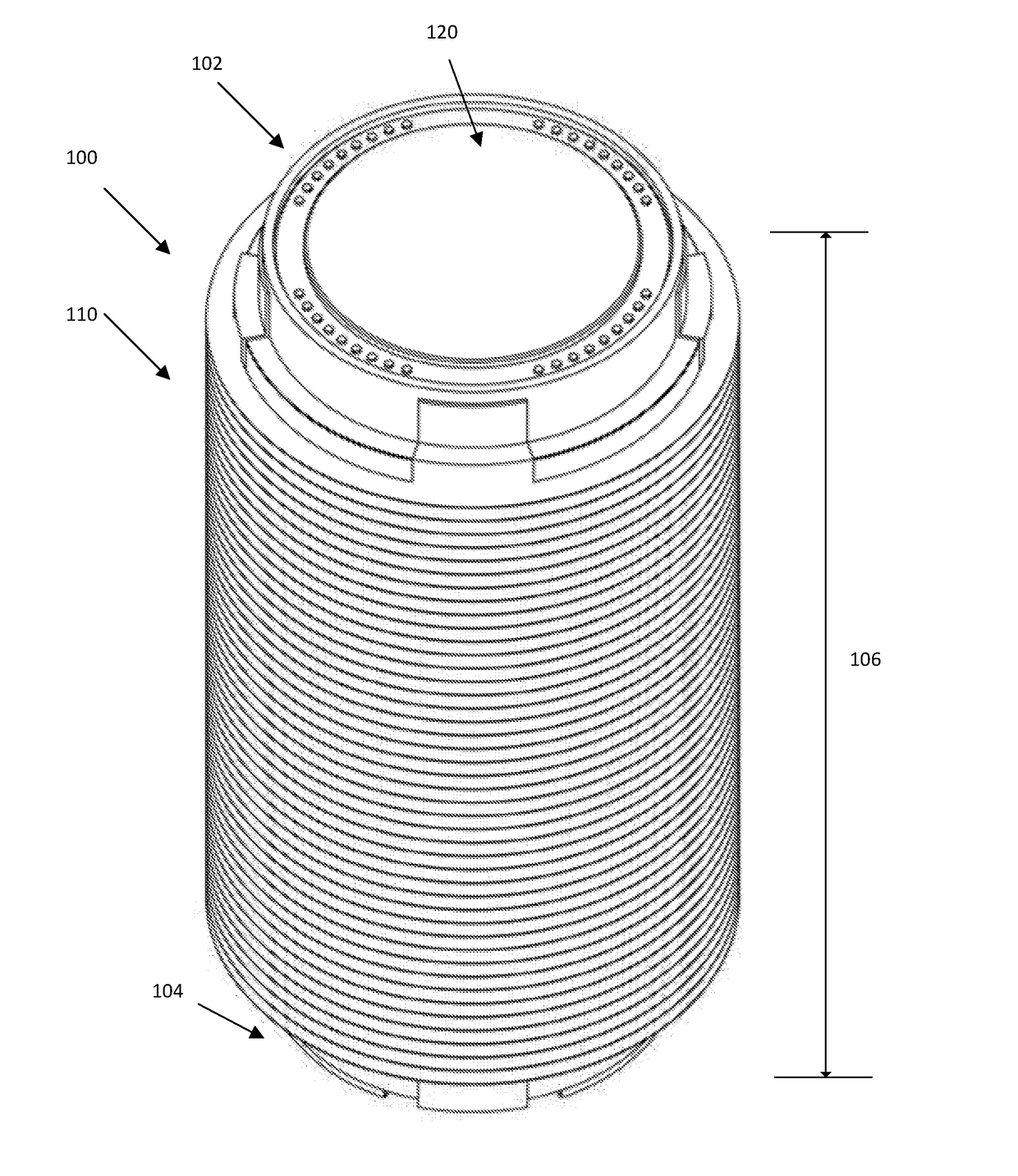
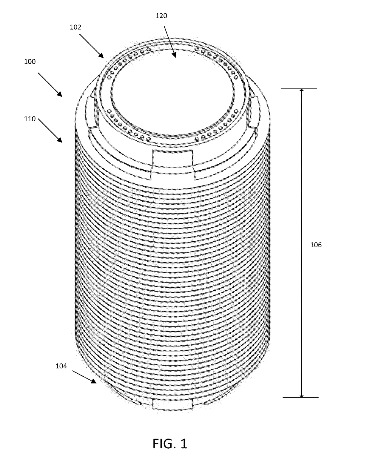
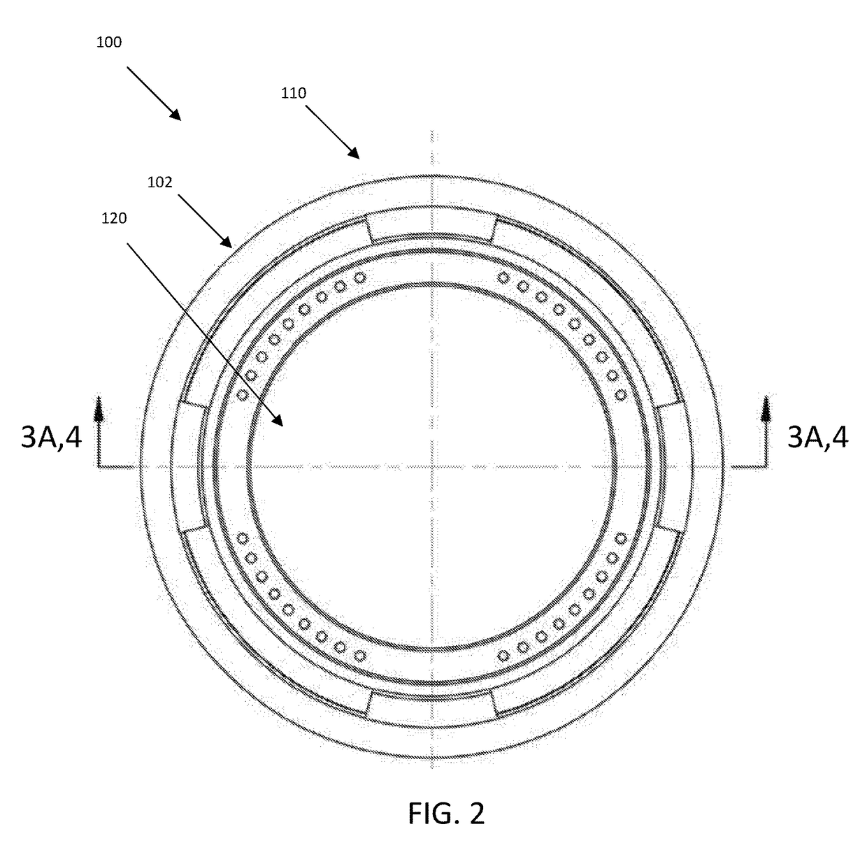
Embodiment Construction

[0028]Various embodiments of fuel storage casks now will be described more fully hereinafter with reference to the accompanying drawings, in which some, but not all embodiments of the fuel storage cask are shown. Indeed, these fuel storage casks may be embodied in many different forms and should not be construed as limited to the embodiments set forth herein; rather, these embodiments are provided so that this disclosure will satisfy applicable legal requirements. The term “or” is used herein in both the alternative and conjunctive sense, unless otherwise indicated. The terms “illustrative” and “exemplary” are used to be examples with no indication of quality level. Terms are used herein both in the singular and plural forms interchangeably. Like numbers refer to like elements throughout.

[0029]Many modifications and other embodiments of the fuel storage casks set forth herein will come to mind to one skilled in the art having the benefit of the teachings presented in the foregoing d...


PUM


Abstract

A fuel storage cask includes an outer shell having a length extending from a first end to a second end of the outer shell, the outer shell defining an inner cavity circumscribed by the outer shell, an outer perimeter extending around the outer shell, an inner perimeter positioned inward from the outer perimeter, and a cooling circuit extending along the length of the outer shell, the cooling circuit including an inner passage, and an outer passage, a coolant positioned within the cooling circuit, where the coolant is configured to move through the inner passage, absorbing heat from the inner cavity of the outer shell, and the coolant is configured to move through the outer passage, dissipating heat through the outer perimeter of the outer shell, and a lid coupled the outer shell, where the lid covers the inner cavity of the outer shell.

Description

CROSS-REFERENCE TO RELATED APPLICATIONS[0001]This application claims priority to U.S. Provisional Patent Application Ser. No. 62 / 372,976 filed on Aug. 10, 2016, which is hereby incorporated by reference in its entirety.BACKGROUND[0002]Nuclear fuel rods are used to generate electrical power, and provide an attractive alternative to the generation of electrical power from fossil fuels. Nuclear fuel rods can be utilized to create a nuclear reaction that may be used to heat water, generating steam to drive a turbine. The turbine may be coupled to a generator, thereby producing electrical energy. Over time, the nuclear fuel rods may become “spent,” and may no longer be useful to sustain a nuclear reaction. While no longer able to sustain a useful nuclear reaction, the nuclear fuel rods may continue to produce heat that must be dissipated and may emit radiation that must be contained.[0003]Conventionally, these spent nuclear fuel rods may be kept within a storage pool for a period of time...

Claims


Application Information

Patent Timeline
IPC IPC(8): G21F5/008G21F5/12G21F5/10
CPCG21F5/008G21F5/10G21F5/12Y02E30/30
Inventor BRIGHT, JONATHAN
Owner BRIGHT JONATHAN
Why Eureka
Eureka Blog
Learn More