
Method of storing high level radioactive waste

a radioactive waste and high-level technology, applied in the field of high-level radioactive waste storage, can solve the problems of high radioactivity of snf, care be taken, and the lowermost region of the vertical canister and the bottom half of the horizontal canister is vulnerable to stress corrosion cracking, so as to reduce the cross-sectional area and mitigate the risk of stress corrosion cracking

Active Publication Date: 2019-05-09
HOLTEC INT
View PDF11 Cites 10 Cited by
  • Summary
  • Abstract
  • Description
  • Claims
  • Application Information

AI Technical Summary

Benefits of technology

This patent is about a method for storing high level radioactive waste in a ventilated system. The method involves positioning a metal canister containing the waste in a cavity of the system. The system has ducts for air to flow in and out of the cavity, which are designed to maintain the temperature of the air as it flows through the system. The method further involves conveying the air into the cavity and reducing the cross-sectional area of the ducts over time to control the temperature of the air. This helps to prevent damage to the waste canister. The technical effect of this method is to provide a safe and secure way to store high level radioactive waste in a ventilated system.

Problems solved by technology

Upon removal, this spent nuclear fuel (“SNF”) is still highly radioactive and produces considerable heat, requiring that great care be taken in its packaging, transporting, and storing.
Stress Corrosion Cracking (SCC) of stainless steel nuclear waste canisters and containers in storage at costal sites with harsh marine environments is an important issue receiving increased industry and regulatory scrutiny.
This means that if there is a sufficient amount of decay heat available, only a short lowermost region of the vertical canister and the bottom half of the horizontal canister are vulnerable to Stress Corrosion Cracking (hereinafter, “SCC”); the balance of the canister is not.
The problem arises, however, when the decay heat progressively declines with the passage of time, the heating of air becomes much slower making a greater portion of the canister vulnerable to SCC.

Method used


Image

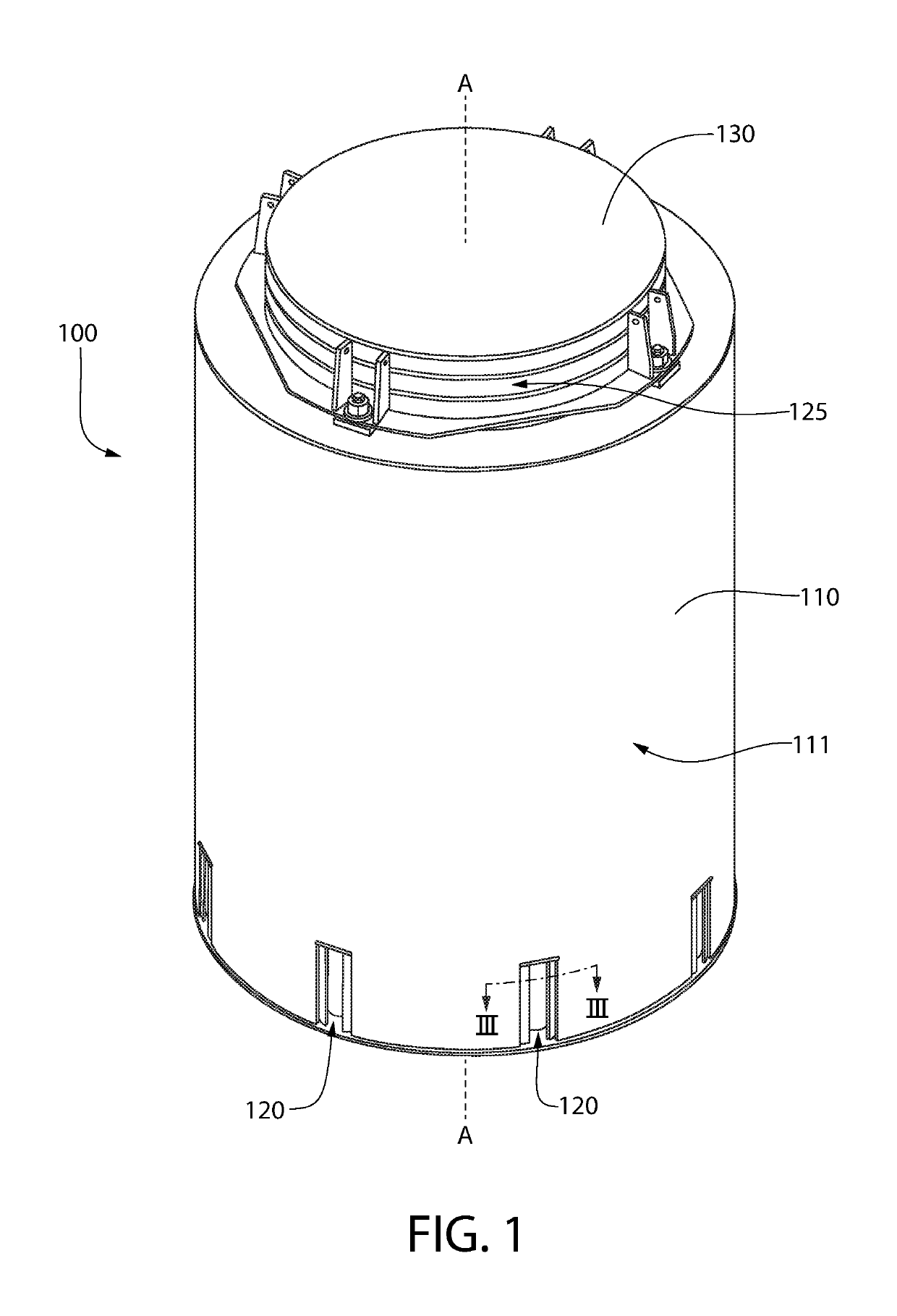
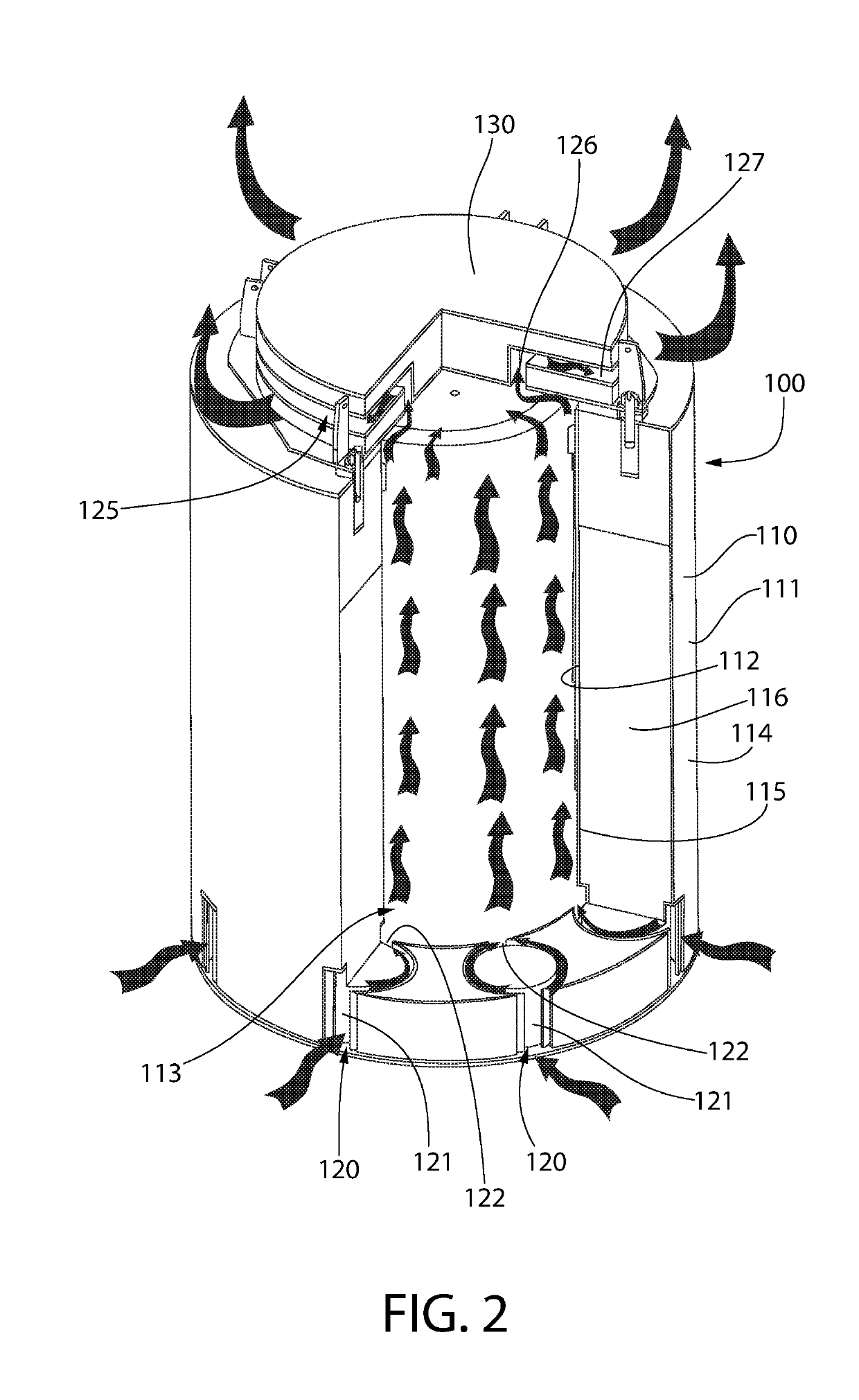
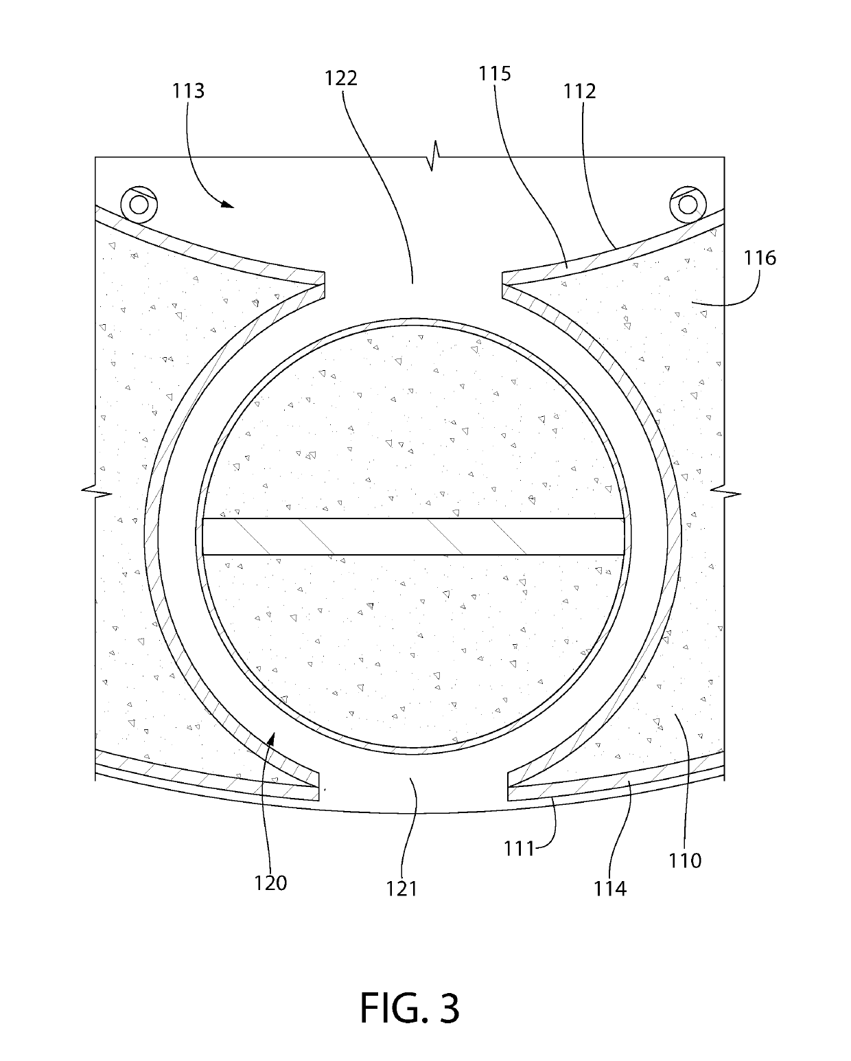
  • Method of storing high level radioactive waste
  • Method of storing high level radioactive waste
  • Method of storing high level radioactive waste

Examples


Embodiment Construction

[0028]The following description of the preferred embodiment(s) is merely exemplary in nature and is in no way intended to limit the invention, its application, or uses.

[0029]The description of illustrative embodiments according to principles of the present invention is intended to be read in connection with the accompanying drawings, which are to be considered part of the entire written description. In the description of embodiments of the invention disclosed herein, any reference to direction or orientation is merely intended for convenience of description and is not intended in any way to limit the scope of the present invention. Relative terms such as “lower,”“upper,”“horizontal,”“vertical,”“above,”“below,”“up,”“down,”“top” and “bottom” as well as derivatives thereof (e.g., “horizontally,”“downwardly,”“upwardly,” etc.) should be construed to refer to the orientation as then described or as shown in the drawing under discussion. These relative terms are for convenience of descript...


PUM


Abstract

A method of storing high level radioactive waste, and specifically a method of adjusting or controlling the temperature of ventilation air flowing through a storage cavity of a ventilated system. The method includes positioning a metal canister containing high level radioactive waste in a storage cavity of the ventilated system. The ventilated system includes a cask body, a cask lid, a plurality of inlet ducts, and at least one outlet duct so that ventilation air can flow from atmosphere into the storage cavity where it is heated and then back out to the atmosphere. The method includes progressively reducing a cross-sectional area of one or more of the inlet ducts and / or the outlet duct over time so that a rate at which the ventilation air is heated within he storage cavity is maintained above a predetermined threshold to mitigate the risk of stress corrosion cracking in the metal canister.

Description

CROSS-REFERENCE TO RELATED PATENT APPLICATIONS[0001]The present application claims the benefit of U.S. Provisional Patent Application Ser. No. 62 / 581,229, filed Nov. 3, 2017, the entirety of which is incorporated herein by reference.BACKGROUND OF THE INVENTION[0002]In the operation of nuclear reactors, it is customary to remove fuel assemblies after their energy has been depleted down to a predetermined level. Upon removal, this spent nuclear fuel (“SNF”) is still highly radioactive and produces considerable heat, requiring that great care be taken in its packaging, transporting, and storing. In order to protect the environment from radiation exposure, SNF is first placed in a canister, which is typically a hermetically sealed canister that creates a confinement boundary about the SNF. The loaded canister is then transported and stored in a large cylindrical container called a cask. Generally, a transfer cask is used to transport spent nuclear fuel from location to location while a ...

Claims


Application Information

Patent Timeline
IPC IPC(8): G21F5/10G21F5/008
CPCG21F5/10G21F5/008G21Y2002/103G21Y2002/104G21Y2004/302Y02E30/30G21F5/005
Inventor SINGH, KRISHNA P.
Owner HOLTEC INT
Learn More