Concrete cylinder-like vessel and its mfg. method

一种制造方法、混凝土的技术,应用在混凝土筒状容器领域,能够解决导热片没有屏蔽体、放射线流出、增加制造的麻烦等问题

Inactive Publication Date: 2004-08-11
KOBE STEEL LTD +1
View PDF2 Cites 10 Cited by
  • Summary
  • Abstract
  • Description
  • Claims
  • Application Information

AI Technical Summary

Problems solved by technology

Furthermore, since there is a part (shield missing part) that cannot be covered by the shield as the opening of the above-mentioned air supply and exhaust port, the outflow of radiation from the opening is unavoidable, which is not desirable.
[0007] In the structure of the above-mentioned patent document 2, since the inner cylinder and the outer cylinder are connected to the whole of both ends of the heat conduction sheet, there is no shielding body on the heat conduction sheet, and there is a problem that radiation passes through the heat conduction sheet and flows out in the radial direction.
Moreover, due to the structure in which the heat conduction sheet is in contact with the inner and outer cylinders, neutron shielding materials such as concrete must be poured in the spaces enclosed by the inner and outer cylinders and the heat conduction sheet, or assembled with block materials, increasing made trouble

Method used


Image

  • Concrete cylinder-like vessel and its mfg. method
  • Concrete cylinder-like vessel and its mfg. method
  • Concrete cylinder-like vessel and its mfg. method

Examples


Embodiment Construction

[0064] Embodiments of the present invention are described below.

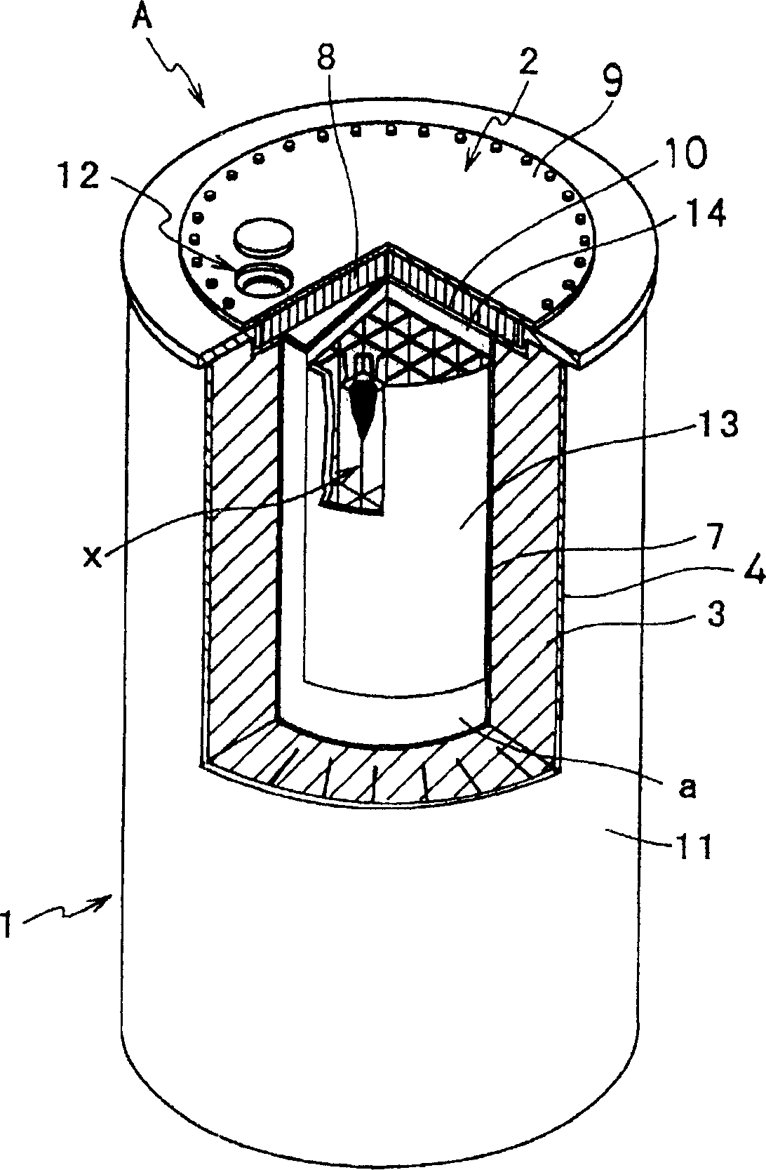
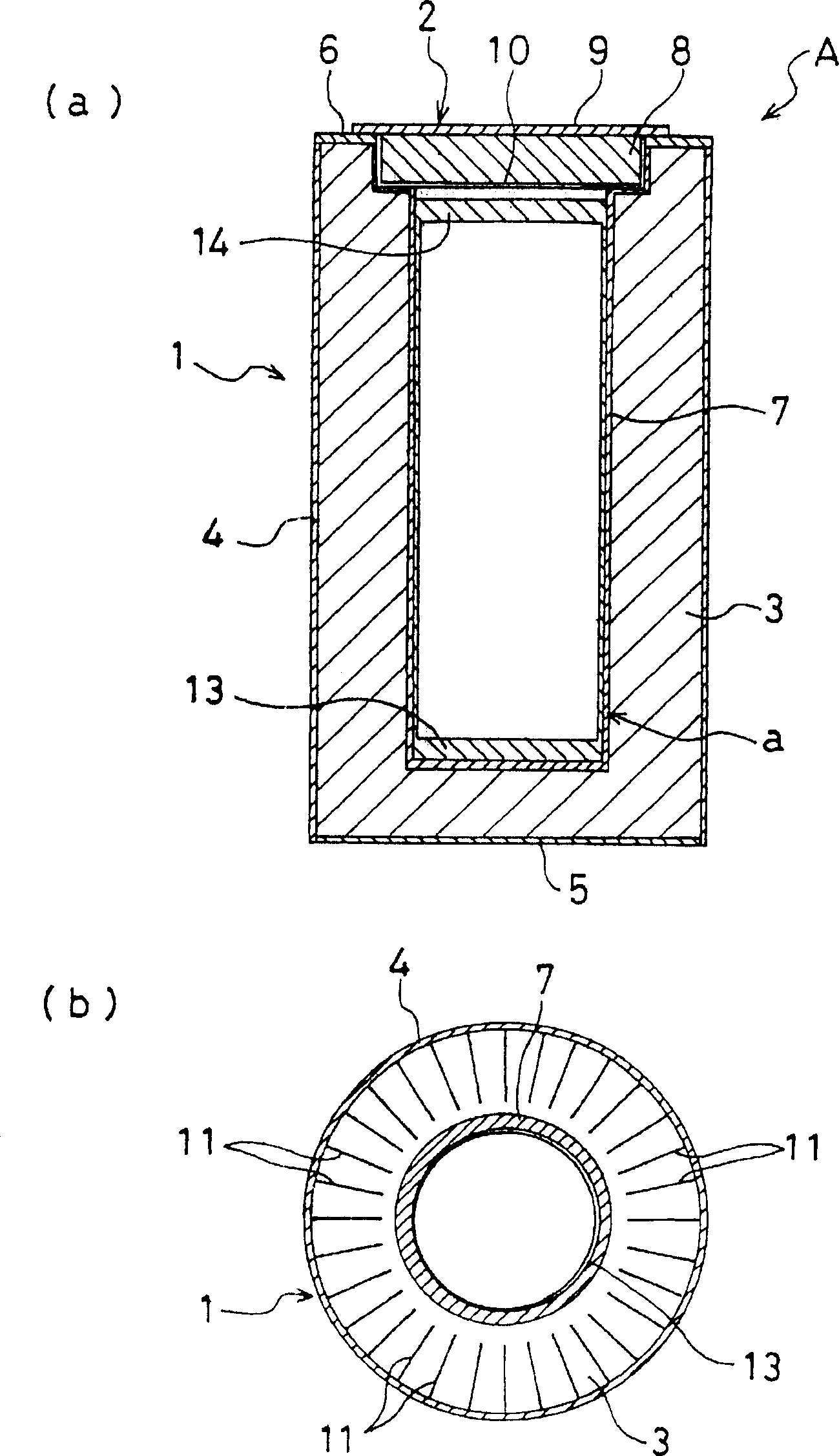
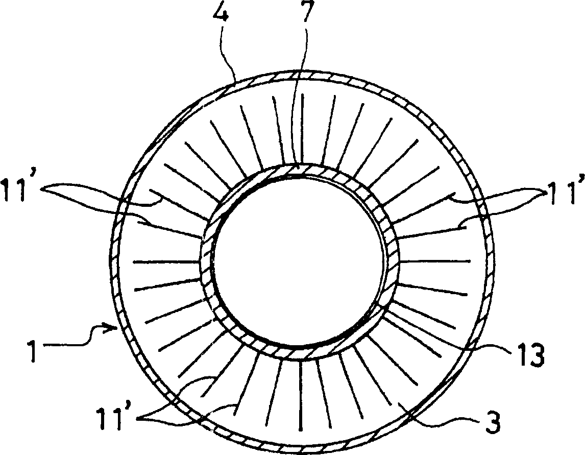
[0065] First, the basic structure of the concrete cylindrical container and the structure of the heat conducting fins in the concrete cylindrical container will be described. figure 1 It is a partially cutaway perspective view showing the storage state of the concrete cylindrical container in the first embodiment of the present invention. figure 2 (a) is a vertical cross-sectional view of the concrete cylindrical container of the first embodiment, and (b) is a cross-sectional view.

[0066] figure 1 and figure 2 The concrete cylindrical container A of the first embodiment shown is composed of a cylindrical container body 1 and a cover 2 with a bottom and no cover. Inside this concrete cylindrical container A is a sealed cylinder a.

[0067] The container body 1 is constructed by covering a concrete container 3 with an outer cylinder 4 made of carbon steel, a bottom cover 5 made of carbon steel, a thicker ...


PUM


Abstract

Provided is a sealed type concrete cask keeping a conventional heat removal performance or having a higher heat removal performance than hitherto, and preventing leak of radioactivity to the outside. This concrete cask A has a formation wherein a shielding body 3 made of concrete and a metal heat-transfer fin 11 are provided between a metal inner cylinder 7 and an outer cylinder 4, and a storage part for storing a radioactive material x is provided inside the inner cylinder 7. The storage part has a sealed structure so as to be blocked from the cask A outside. The heat-transfer fin 11 is provided so that its outer cylinder 4 side part is in contact with the outer cylinder 4, and is notched so that its inner cylinder 7 side part forms a separate part relative to the inner cylinder 7.

Description

technical field [0001] The invention relates to a concrete cylindrical container suitable for transporting or storing radioactive materials such as used nuclear fuel for a long time. Background technique [0002] As conventional concrete cylindrical containers, those described in Patent Document 1 and Patent Document 2 below are known. Patent Document 1 is a typical conventional concrete cylindrical container, and an exhaust port is provided in the upper part of the concrete cylindrical container, and an air supply port is provided in the lower part. This structure is for the external air to enter from the air supply port and discharge from the exhaust port, and to form convection in the gap between the concrete cylindrical container and the sealed cylinder, thus to the sealed cylinder stored inside the concrete cylindrical container ( A structure that removes heat from a sealed container that contains used fuel. [0003] Patent Document 2 has a structure of a metal cylind...

Claims


Application Information

Patent Timeline
Patent Type & Authority Applications(China)
IPC IPC(8): G21C19/32G21C19/06G21F1/04G21F5/005G21F5/008G21F5/10G21F9/36
CPCG21F5/008G21F1/04G21F9/36G21F5/10A47J43/07
Inventor 下条纯谷内广明杉原丰大胁英司畑明仁平川胜彦宫原茂祯
Owner KOBE STEEL LTD
Why Eureka
Try Eureka