Sacrificial layer for protection during trench etch

Active Publication Date: 2007-04-17
LAM RES CORP
View PDF3 Cites 14 Cited by
  • Summary
  • Abstract
  • Description
  • Claims
  • Application Information

AI Technical Summary

Benefits of technology

[0004]Broadly speaking, the present invention fills these needs by providing a method and apparatus for substantially eliminating the voids caused by lateral etching during the etch process without significantly affecting th

Problems solved by technology

In addition, a photoresist layer may or may not be disposed on top of the silicon dioxide layer: Dry etch plasma reactors utilizing inductive coupled plasma technology (ICP) designed for silicon etch applications are limited in performing the silic

Method used


Image

  • Sacrificial layer for protection during trench etch
  • Sacrificial layer for protection during trench etch
  • Sacrificial layer for protection during trench etch

Examples


Embodiment Construction

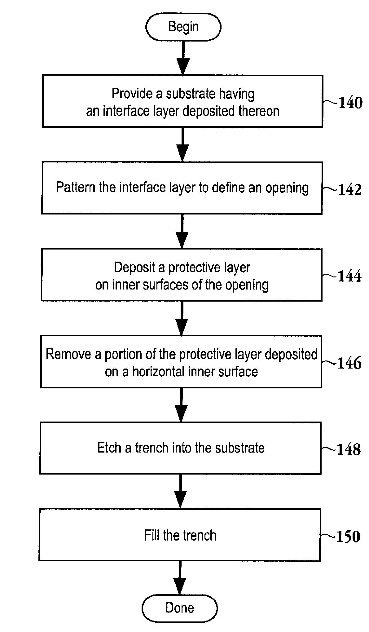
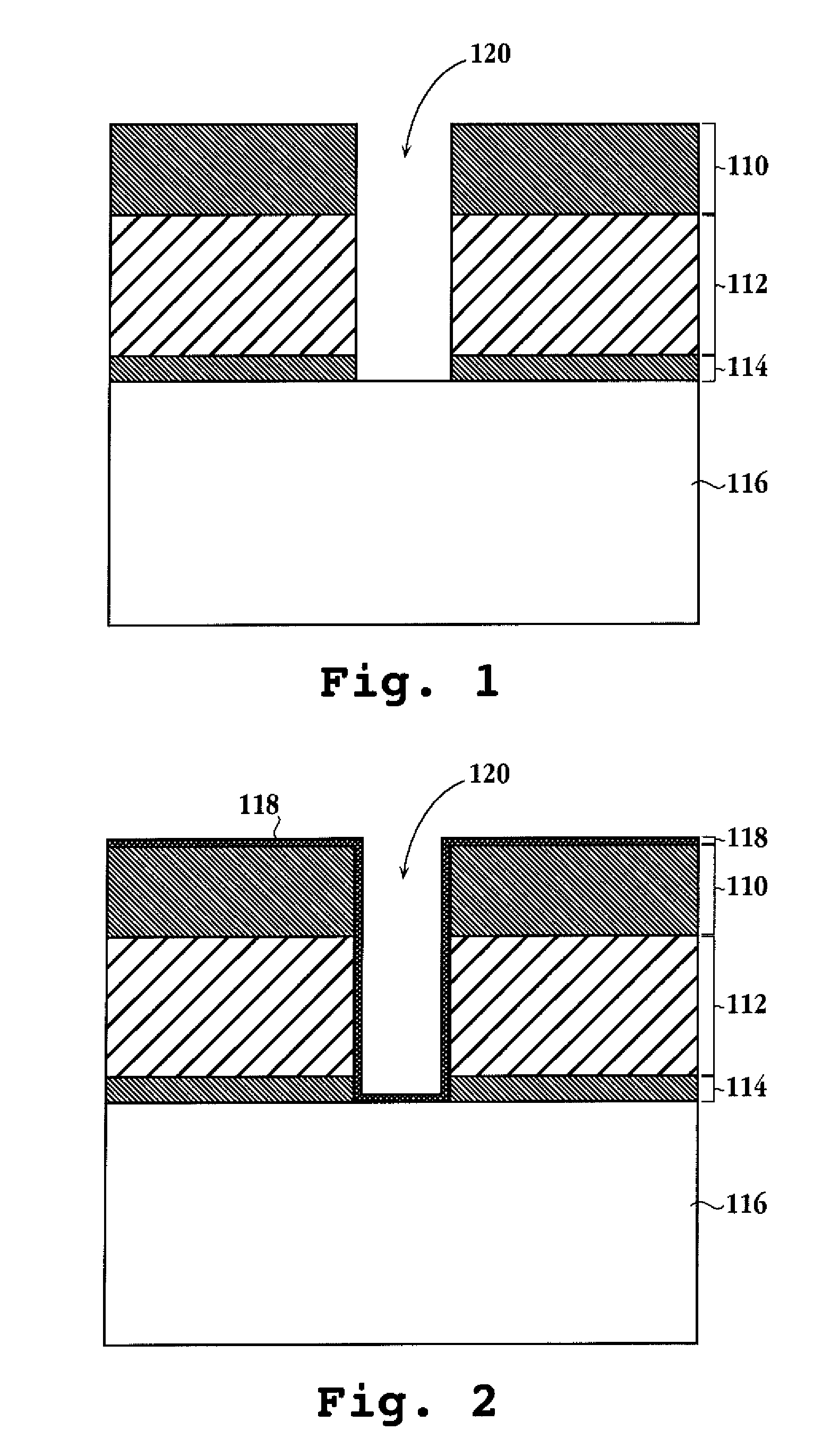
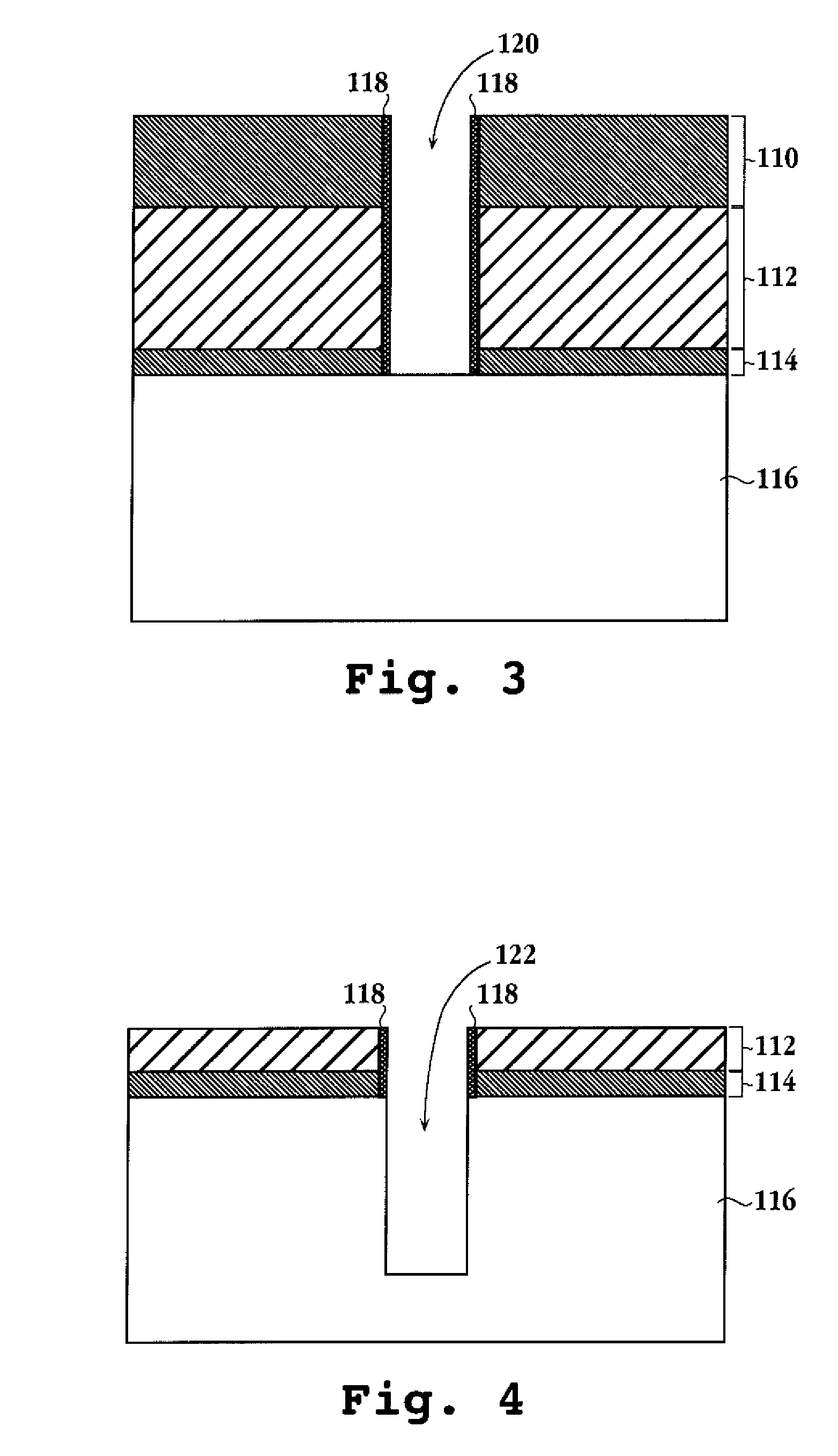
[0018]An invention is described for a system and method for defining a trench within a substrate in a manner that avoids the lateral etching of a thin layer disposed over the surface of the substrate being etched. It will be obvious, however, to one skilled in the art, that the present invention may be practiced without some or all of these specific details. In other instances, well known process operations have not been described in detail in order not to unnecessarily obscure the present invention.

[0019]The embodiments of the present invention provide a system and method for etching a substrate in a manner that prevents the lateral etching of a thin stop layer disposed on the substrate being etched. In one embodiment, a gas modulation technique is utilized to alternate between a deposition phase and an etch phase in a processing chamber to incrementally etch the feature in a single processing chamber. The deposition phase defines a protection layer that prevents the lateral attack...


PUM


Abstract

A method for etching a trench is provided. The method initiates with providing a substrate having a patterned feature. The method includes alternating between deposition of a protective layer onto inner surfaces of the patterned feature and etching the trench into the substrate. The alternating may be achieved through a gas modulation technique and in one embodiment, the deposition and the etching are performed in the same chamber, i.e., the substrate does not move to a different chamber between the etch and deposition processes. The alternating is continued until the trench is completed and then the trench is filled. A semiconductor processing system is also provided.

Description

CROSS REFERENCE TO RELATED APPLICATIONS[0001]This application claims priority from U.S. Provisional Patent Application No. 60 / 656,785, filed on Feb. 24, 2005 and entitled “SACRIFICIAL LAYER FOR PROTECTION DURING DEEP SILICON TRENCH ETCH,” which is incorporated herein by reference in its entirety for all purposes.BACKGROUND OF THE INVENTION[0002]During the manufacturing of semiconductor-based devices, it is common to etch features, such as a trench, into a substrate. One exemplary film stack employed when etching a trench into a silicon substrate includes a mask composed of a thick silicon dioxide layer on top of a second thin layer, e.g., a silicon nitride layer, which is disposed over the silicon substrate. The silicon nitride layer is typically present as either an etch stop for subsequent CMP applications or as a stress relief for the underlying silicon layer. In addition, a photoresist layer may or may not be disposed on top of the silicon dioxide layer: Dry etch plasma reactors...

Claims


Application Information

Patent Timeline
IPC IPC(8): H01L21/4763
CPCH01L21/30655H01L21/3086H01L21/76898
Inventor SCHAEFER, DAVIDCHARATAN, ROBERT
Owner LAM RES CORP
Why Eureka
Try Eureka